is that more visible please need a reply soon

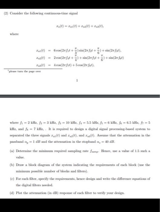
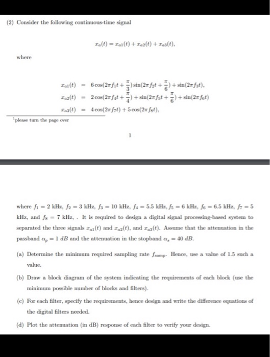
Consider the following continuous-time signal 1.(t) = 1/(t) +12(t) + 13(t), where Tal(t) 6.cos(2=fit + 5) sin(25f2t + 5) + sin(2=fst), T2(t) - 2 cos(2=fut + ) + sin(27fst + 5) + sin(2=fet) Taj(t) = 4.cos(2=f7t) +5 cos(2=fst), please turn the page over where f1 = 2 kHz, f2 = 3 kHz, fs = 10 kHz, fa = 5.5 kHz, fs = 6 kHz, fe = 6.5 kHz, f7 = 5 kHz, and fs = 7 kHz,. It is required to design a digital signal processing-based system to separated the three signals Ia(t) and 142(t), and 1s(t). Assume that the attemnation in the passband a, = 1 dB and the attenuation in the stopband a = 40 dB. (a) Determine the minimum required sampling rate framp. Hence, use a value of 1.5 such a value. (b) Draw a block diagram of the system indicating the requirements of each block (use the minimum possible number of blocks and filters). (c) For each filter, specify the requirements, hence design and write the difference equations of the digital filters needed (d) Plot the attenuation (in dB) response of each filter to verify your design. Consider the following continuous-time signal 1.(t) = Tal(t) + 122(t) + 13(t), where Tal(t) - 6008(2=fit + 5) sin(25f2t + 5) + sin(2=fst), 12(t) - 2 cos(2=fet + ) + sin(27fst + 5) + sin(2=fet) Taj(t) = 4.cos(2=f7t) +5.cos(2=fst), please turn the page over where f1 = 2 kHz, f2 = 3 kHz, fs = 10 kHz, fa = 5.5 kHz, fs = 6 kHz, fs = 6.5 kHz, f7 = 5 kHz, and fs = 7 kHz,. It is required to design a digital signal processing-based system to separated the three signals Ia(t) and 142(t), and 1s(t). Assume that the attemnation in the passband a, = 1 dB and the attenuation in the stopband a, = 40 dB. (a) Determine the minimum required sampling rate framp. Hence, use a value of 1.5 such a value. (b) Draw a block diagram of the system indicating the requirements of each block (use the minimum possible number of blocks and filters). (C) For each filter, specify the requirements, hence design and write the difference equations of the digital filters needed. (d) Plot the attenuation (in dB) response of each filter to verify your design. Consider the following continuous-time signal 1.(t) = 1/(t) +12(t) + 13(t), where Tal(t) 6.cos(2=fit + 5) sin(25f2t + 5) + sin(2=fst), T2(t) - 2 cos(2=fut + ) + sin(27fst + 5) + sin(2=fet) Taj(t) = 4.cos(2=f7t) +5 cos(2=fst), please turn the page over where f1 = 2 kHz, f2 = 3 kHz, fs = 10 kHz, fa = 5.5 kHz, fs = 6 kHz, fe = 6.5 kHz, f7 = 5 kHz, and fs = 7 kHz,. It is required to design a digital signal processing-based system to separated the three signals Ia(t) and 142(t), and 1s(t). Assume that the attemnation in the passband a, = 1 dB and the attenuation in the stopband a = 40 dB. (a) Determine the minimum required sampling rate framp. Hence, use a value of 1.5 such a value. (b) Draw a block diagram of the system indicating the requirements of each block (use the minimum possible number of blocks and filters). (c) For each filter, specify the requirements, hence design and write the difference equations of the digital filters needed (d) Plot the attenuation (in dB) response of each filter to verify your design. Consider the following continuous-time signal 1.(t) = Tal(t) + 122(t) + 13(t), where Tal(t) - 6008(2=fit + 5) sin(25f2t + 5) + sin(2=fst), 12(t) - 2 cos(2=fet + ) + sin(27fst + 5) + sin(2=fet) Taj(t) = 4.cos(2=f7t) +5.cos(2=fst), please turn the page over where f1 = 2 kHz, f2 = 3 kHz, fs = 10 kHz, fa = 5.5 kHz, fs = 6 kHz, fs = 6.5 kHz, f7 = 5 kHz, and fs = 7 kHz,. It is required to design a digital signal processing-based system to separated the three signals Ia(t) and 142(t), and 1s(t). Assume that the attemnation in the passband a, = 1 dB and the attenuation in the stopband a, = 40 dB. (a) Determine the minimum required sampling rate framp. Hence, use a value of 1.5 such a value. (b) Draw a block diagram of the system indicating the requirements of each block (use the minimum possible number of blocks and filters). (C) For each filter, specify the requirements, hence design and write the difference equations of the digital filters needed. (d) Plot the attenuation (in dB) response of each filter to verify your design


