 Answer Part 2 Please
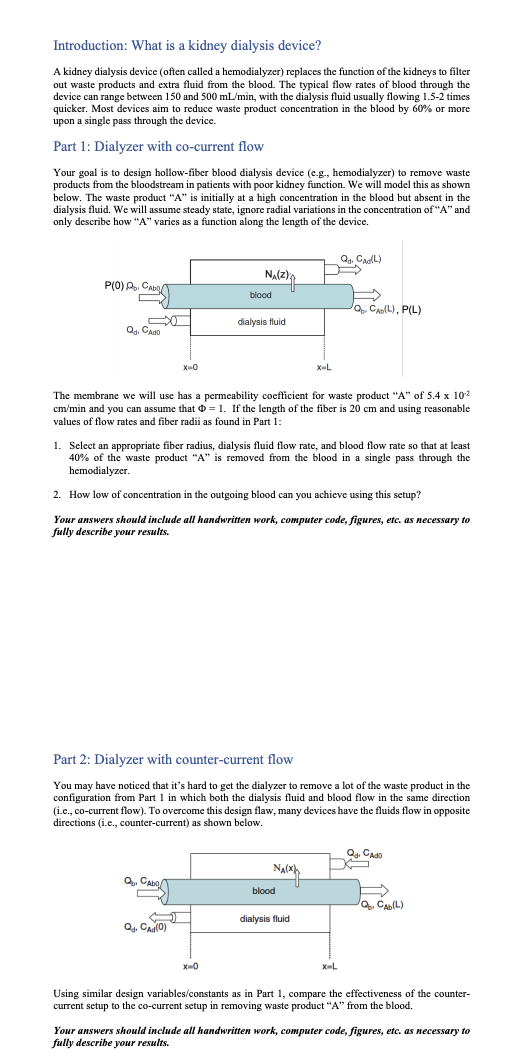
Introduction: What is a kidney dialysis device? A kidney dialysis device (often called a hemodialyzer) replaces the function of the kidneys to filter out waste products and extra fluid from the blood. The typical flow rates of blood through the device can range between 150 and 500mL/min, with the dialysis fluid usually flowing 1.52 times quicker. Most devices aim to reduce waste product concentration in the blood by 60% or more upon a single pass through the device. Part 1: Dialyzer with co-current flow Your goal is to design hollow-fiber blood dialysis device (e.g., hemodialyzer) to remove waste products from the bloodstream in patients with poor kidney function. We will model this as shown below. The waste product " A " is initially at a high concentration in the blood but absent in the dialysis fluid. We will assume steady state, ignore radial variations in the concentration of " A " and only describe how " A " varies as a function along the length of the device. The membrane we will use has a permeability coefficient for waste product " A " of 5.4102 cm/min and you can assume that =1. If the length of the fiber is 20cm and using reasonable values of flow rates and fiber radii as found in Part 1 : 1. Select an appropriate fiber radius, dialysis fluid flow rate, and blood flow rate so that at least 40% of the waste product "A" is removed from the blood in a single pass through the hemodialyzer. 2. How low of concentration in the outgoing blood can you achieve using this setup? Your answers should include all handwritten work, computer code, figures, etc. as necessary to fully describe your results. Part 2: Dialyzer with counter-current flow You may have noticed that it's hard to get the dialyzer to remove a lot of the waste product in the configuration from Part 1 in which both the dialysis fluid and blood flow in the same direction (i.e., co-current flow). To overcome this design flaw, many devices have the fluids flow in opposite directions (i.e., counter-current) as shown below. Using similar design variables/constants as in Part 1, compare the effectiveness of the countercurrent setup to the co-current setup in removing waste product "A" from the blood. Your answers should include all handwritten work, computer code, figures, etc. as necessary to fully describe your results
 Answer Part 2 Please


