

Answered step by step
Verified Expert Solution
Question
1 Approved Answer
. Answers of g and h needed only. In form of Matlab code please. The figure shows the pendulum on a cart system. The position
 .
.
Answers of g and h needed only. In form of Matlab code please.
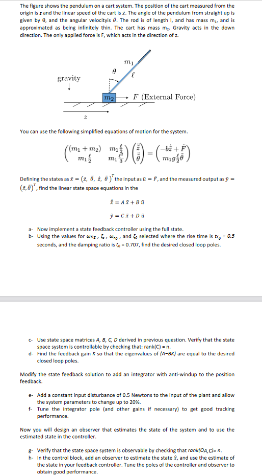
The figure shows the pendulum on a cart system. The position of the cart measured from the origin is z and the linear speed of the cart is . The angle of the pendulum from straight up is given by 6, and the angular velocityis d. The rod is of length I, and has mass me, and is approximated as being infinitely thin. The cart has mass mz. Gravity acts in the down direction. The only applied force is F, which acts in the direction of z. mi gravity 1 TI2 F (External Force) You can use the following simplified equations of motion for the system. ( (m + m2) mi -b + F mig Defining the states as i = (2, 7, , 7)"the input as = F, and the measured output as y (7,4)", find the linear state space equations in the * = A2+B = C = + D a. Now implement a state feedback controller using the full state. b- Using the values for wnz, 6, Wag, and selected where the rise time is tro = 0.5 seconds, and the damping ratio is = 0.707, find the desired closed loop poles. Use state space matrices A, B, C, D derived in previous question. Verify that the state space system is controllable by checking that: rank(C) = n. d- Find the feedback gain K so that the eigenvalues of (A-BK) are equal to the desired closed loop poles. Modify the state feedback solution to add an integrator with anti-windup to the position feedback - Add a constant input disturbance of 0.5 Newtons to the input of the plant and allow the system parameters to change up to 20%. f- Tune the integrator pole (and other gains if necessary) to get good tracking performance. Now you will design an observer that estimates the state of the system and to use the estimated state in the controller. & Verify that the state space system is observable by checking that ronk(OA,C)= n. - In the control block, add an observer to estimate the state #, and use the estimate of the state in your feedback controller. Tune the poles of the controller and observer to obtain good performance. The figure shows the pendulum on a cart system. The position of the cart measured from the origin is z and the linear speed of the cart is . The angle of the pendulum from straight up is given by 6, and the angular velocityis d. The rod is of length I, and has mass me, and is approximated as being infinitely thin. The cart has mass mz. Gravity acts in the down direction. The only applied force is F, which acts in the direction of z. mi gravity 1 TI2 F (External Force) You can use the following simplified equations of motion for the system. ( (m + m2) mi -b + F mig Defining the states as i = (2, 7, , 7)"the input as = F, and the measured output as y (7,4)", find the linear state space equations in the * = A2+B = C = + D a. Now implement a state feedback controller using the full state. b- Using the values for wnz, 6, Wag, and selected where the rise time is tro = 0.5 seconds, and the damping ratio is = 0.707, find the desired closed loop poles. Use state space matrices A, B, C, D derived in previous question. Verify that the state space system is controllable by checking that: rank(C) = n. d- Find the feedback gain K so that the eigenvalues of (A-BK) are equal to the desired closed loop poles. Modify the state feedback solution to add an integrator with anti-windup to the position feedback - Add a constant input disturbance of 0.5 Newtons to the input of the plant and allow the system parameters to change up to 20%. f- Tune the integrator pole (and other gains if necessary) to get good tracking performance. Now you will design an observer that estimates the state of the system and to use the estimated state in the controller. & Verify that the state space system is observable by checking that ronk(OA,C)= n. - In the control block, add an observer to estimate the state #, and use the estimate of the state in your feedback controller. Tune the poles of the controller and observer to obtain good performanceStep by Step Solution
There are 3 Steps involved in it
Step: 1

Get Instant Access to Expert-Tailored Solutions
See step-by-step solutions with expert insights and AI powered tools for academic success
Step: 2

Step: 3
Ace Your Homework with AI
Get the answers you need in no time with our AI-driven, step-by-step assistance
Get Started
Fundamentals Of Database Management Systems
Authors: Mark L. Gillenson
2nd Edition
0470624701, 978-0470624708