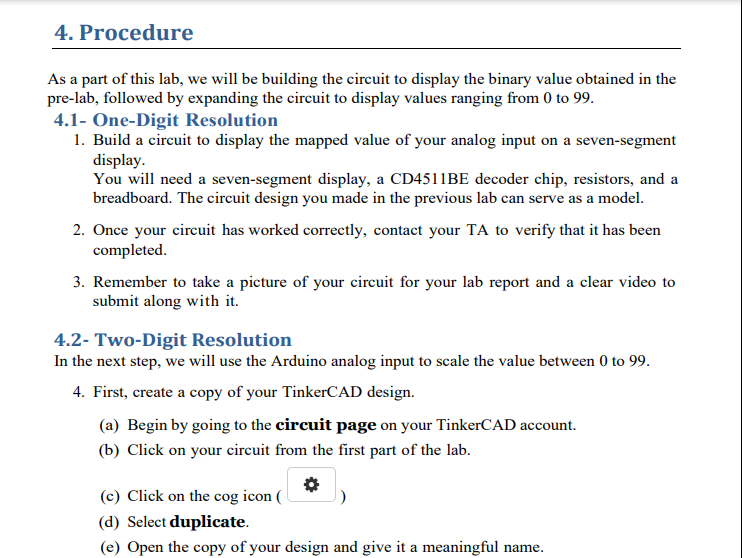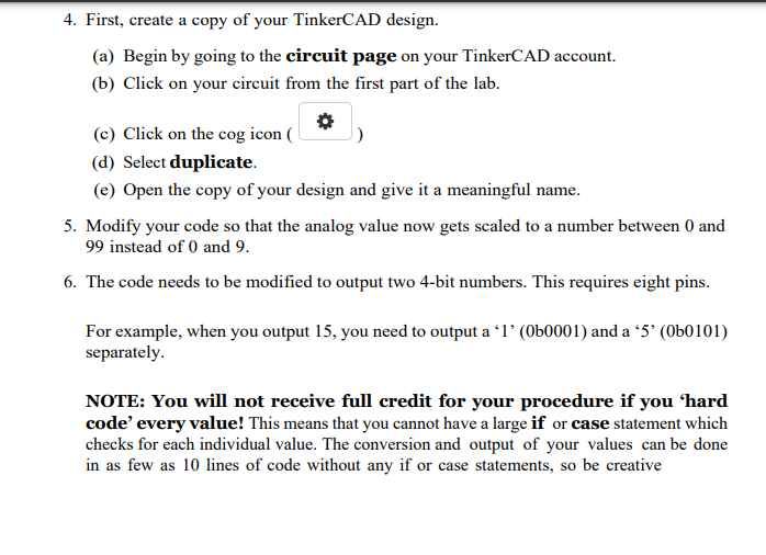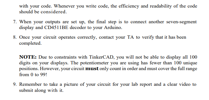


As a part of this lab, we will be building the circuit to display the binary value obtained in the pre-lab, followed by expanding the circuit to display values ranging from 0 to 99 . 4.1- One-Digit Resolution 1. Build a circuit to display the mapped value of your analog input on a seven-segment display. You will need a seven-segment display, a CD4511BE decoder chip, resistors, and a breadboard. The circuit design you made in the previous lab can serve as a model. 2. Once your circuit has worked correctly, contact your TA to verify that it has been completed. 3. Remember to take a picture of your circuit for your lab report and a clear video to submit along with it. 4.2- Two-Digit Resolution In the next step, we will use the Arduino analog input to scale the value between 0 to 99. 4. First, create a copy of your TinkerCAD design. (a) Begin by going to the circuit page on your TinkerCAD account. (b) Click on your circuit from the first part of the lab. (c) Click on the cog icon ( ) (d) Select duplicate. (e) Open the copy of your design and give it a meaningful name. 4. First, create a copy of your TinkerCAD design. (a) Begin by going to the circuit page on your TinkerCAD account. (b) Click on your circuit from the first part of the lab. (c) Click on the cogicon( ) (d) Select duplicate. (e) Open the copy of your design and give it a meaningful name. 5. Modify your code so that the analog value now gets scaled to a number between 0 and 99 instead of 0 and 9. 6. The code needs to be modified to output two 4-bit numbers. This requires eight pins. For example, when you output 15 , you need to output a ' 1 ' (0b0001) and a ' 5 ' (0b0101) separately. NOTE: You will not receive full credit for your procedure if you 'hard code' every value! This means that you cannot have a large if or case statement which checks for each individual value. The conversion and output of your values can be done in as few as 10 lines of code without any if or case statements, so be creative with your code. Whenever you write code, the efficiency and readability of the code should be considered. 7. When your outputs are set up, the final step is to connect another seven-segment display and CD4511BE decoder to your Arduino. 8. Once your circuit operates correctly, contact your TA to verify that it has been completed. NOTE: Due to constraints with TinkerCAD, you will not be able to display all 100 digits on your displays. The potentiometer you are using has fewer than 100 unique positions. However, your circuit must only count in order and must cover the full range from 0 to 99 ! 9. Remember to take a picture of your circuit for your lab report and a clear video to submit along with it


