Question: Assignment Brief The S.W.E.A.T Lab is currently upgrading the conveyor line to meet Industry 4.0 standards where a central PLC with a MES system governing
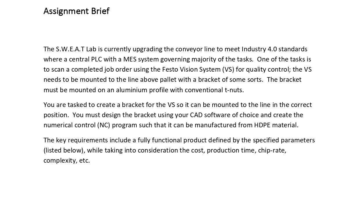
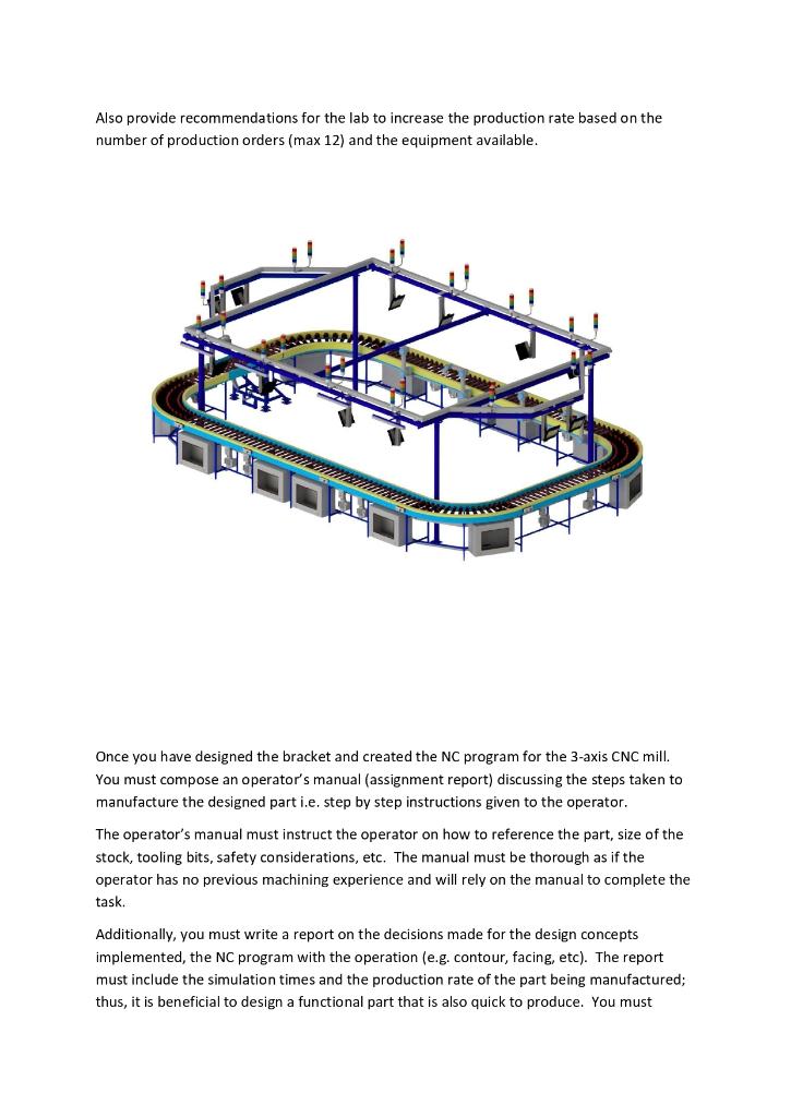
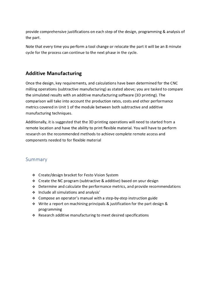
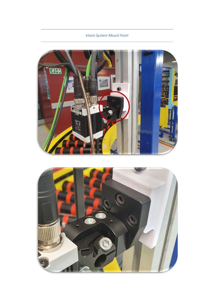
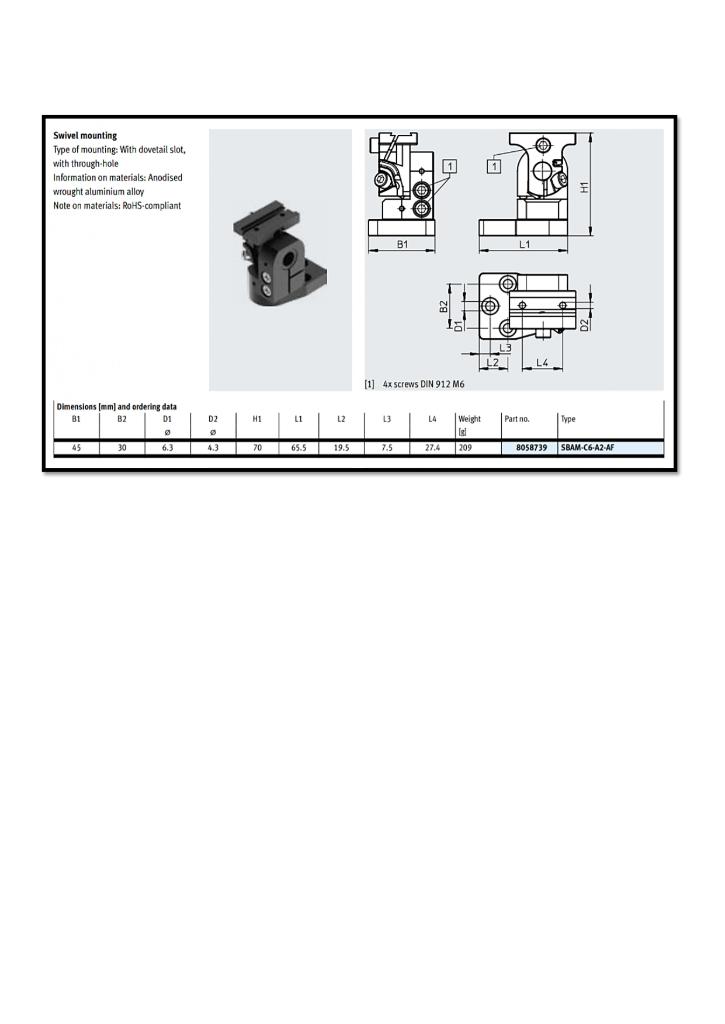
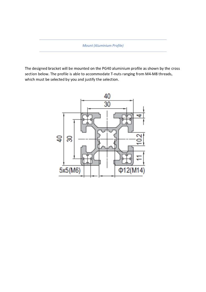
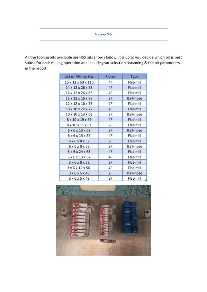
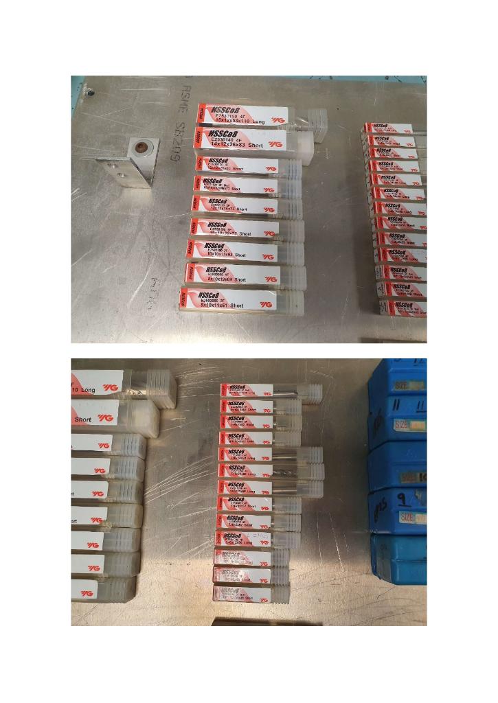
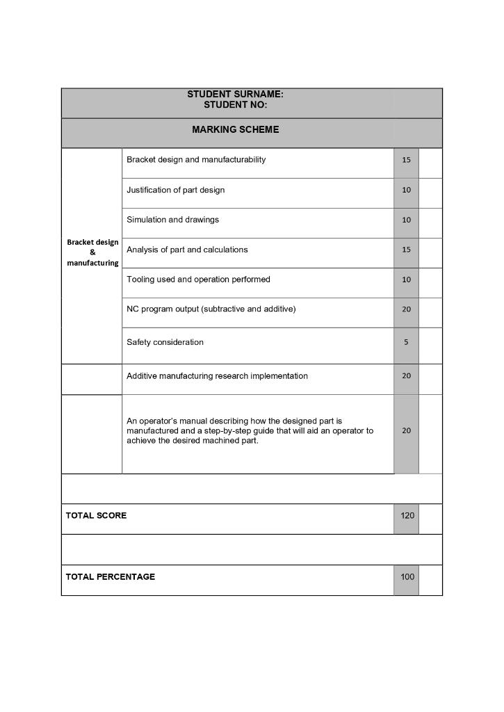
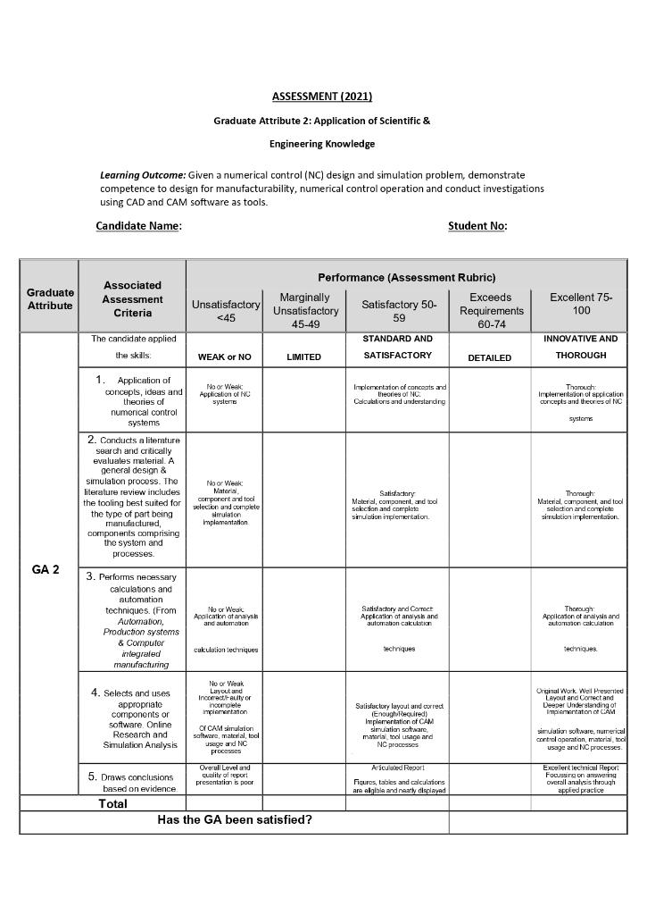
Assignment Brief The S.W.E.A.T Lab is currently upgrading the conveyor line to meet Industry 4.0 standards where a central PLC with a MES system governing majority of the tasks. One of the tasks is to scan a completed job order using the Festo Vision System (VS) for quality control; the VS needs to be mounted to the line above pallet with a bracket of some sorts. The bracket must be mounted on an aluminium profile with conventional t-nuts. You are tasked to create a bracket for the VS so it can be mounted to the line in the correct position. You must design the bracket using your CAD software of choice and create the numerical control (NC) program such that it can be manufactured from HDPE material. The key requirements include a fully functional product defined by the specified parameters (listed below), while taking into consideration the cost, production time, chip-rate, complexity, etc. Also provide recommendations for the lab to increase the production rate based on the number of production orders (max 12) and the equipment available. Once you have designed the bracket and created the NC program for the 3-axis CNC mill. You must compose an operator's manual (assignment report) discussing the steps taken to manufacture the designed part i.e. step by step instructions given to the operator. The operator's manual must instruct the operator on how to reference the part, size of the stock, tooling bits, safety considerations, etc. The manual must be thorough as if the operator has no previous machining experience and will rely on the manual to complete the task. Additionally, you must write a report on the decisions made for the design concepts implemented, the NC program with the operation (e.g. contour, facing, etc). The report must include the simulation times and the production rate of the part being manufactured; thus, it is beneficial to design a functional part that is also quick to produce. You must provide comprehensive justifications on each step of the design, programming & analysis of the part. Note that every time you perform a tool change or relocate the part it will be an 8 minute cycle for the process can continue to the next phase in the cycle. Additive Manufacturing Once the design, key requirements, and calculations have been determined for the CNC milling operations (subtractive manufacturing) as stated above; you are tasked to compare the simulated results with an additive manufacturing software (3D printing). The comparison will take into account the production rates, costs and other performance metrics covered in Unit 1 of the module between both subtractive and additive manufacturing techniques. Additionally, it is suggested that the 3D printing operations will need to started from a remote location and have the ability to print flexible material. You will have to perform research on the recommended methods to achieve complete remote access and components needed to for flexible material Summary * Create/design bracket for Festo Vision System Create the NC program (subtractive & additive) based on your design Determine and calculate the performance metrics, and provide recommendations Include all simulations and analysis' * Compose an operator's manual with a step-by-step instruction guide Write a report on machining principals & justification for the part design & programming Research additive manufacturing to meet desired specifications Vision System Mount Point SEASON WENDA Swivel mounting Type of mounting With dovetail stot, with through hole Information on materials: Anodised wrought aluminium alloy Note on materials: RoHS compliant B1 L1 za al- TL [1] 4x screws DIN 912 M6 Dimensions (mm) and ordering data BI B2 01 HI LI L2 L3 L4 Partno Type D2 . 4. Weight Isl 45 30 6.3 70 65.5 19.5 7.5 27.4 209 8058739 SBAM-C6-A2-AF Mount (Aluminium Profile) The designed bracket will be mounted on the PG40 aluminium profile as shown by the cross section below. The profile is able to accommodate T-nuts ranging from M4-M8 threads, which must be selected by you and justify the selection. 40 30 141 40 30 11 10.2 5x5(M6) 012(M14) Tooling Bits All the tooling bits available are HSS bits shown below; it is up to you decide which bit is best suited for each milling operation and include your selection reasoning & the bit parameters in the report. List of Milling-Bits Flutes Type 15 x 12 x 53 x 110 4F Flat-mill 14 x 12 x 26 x 83 4F Flat-mill 12 x 12 x 26 x 83 4F Flat-mill 12 x 12 x 16 x 73 2F Ball-nose 12 x 12 x 16 x 73 2F Flat-mill 10 x 10 x 22 x 72 4F Flat-mill 10 x 10 x 13 x 63 2F Ball-nose 8 x 10 x 19 x 69 4F Flat-mill 8 x 10 x 11 x 61 2F Flat-mill 6 x 6 x 13 x 68 2F Ball-nose 6 x 6 x 13 x 57 4F Flat-mill 6x6x8x52 2F Flat-mill 6x6x8 x 52 2F Ball-nose 5x 6 x 24 x 68 4F Flat-mill 5x6x 13 x 57 4F Flat-mill 56852 2F Flat-mill 3 x 6 x 12 x 56 4F Flat-mill 3 x 6 x 5 x 49 2F Ball-nose 3 x 6 x 5 x 49 2F Flat-mill 9. NSSCOS E350 4F 16x12x11o Lang -96 HSSCos E25301404 14x12x26083 Short WG RESEP GE AWAR ASSCOR es 12 Short seat MENEW S698 WS! G ACAS ES 12x160738 MSSR sten RES 8SSEN FO 9. Short G SED ISSCAS 10da1.18 Short escor "G WG SEN ASSICA 80x196 Short 36 Assol E2533000 a Box11x61 Short G Coo 10 Long G VG Short WG that 9 SCOP . SIZE ASSCOP LA G Sce M YO 29G AM ASSEN th ASSOS O4 1 296 9 . 90 us 96 ARCO ort SIZE Red 996 G G STUDENT SURNAME: STUDENT NO: MARKING SCHEME Bracket design and manufacturability 15 Justification of part design 10 Simulation and drawings 10 Bracket design & manufacturing Analysis of part and calculations 15 Tooling used and operation performed 10 NC program output (subtractive and additive) 20 Safety consideration 5 Additive manufacturing research implementation 20 An operator's manual describing how the designed part is manufactured and a step-by-step guide that will aid an operator to achieve the desired machined part. 20 TOTAL SCORE 120 TOTAL PERCENTAGE 100 ASSESSMENT (2021) Graduate Attribute 2: Application of Scientific & Engineering Knowledge Learning Outcome: Given a numerical control (NC) design and simulation problem, demonstrate competence to design for manufacturability, numerical control operation and conduct investigations using CAD and CAM software as tools. Candidate Name: Student No: Graduate Attribute Associated Assessment Criteria Excellent 75 100 Performance (Assessment Rubric) Marginally Exceeds Unsatisfactory Unsatisfactory Satisfactory 50- Requirements
Step by Step Solution
There are 3 Steps involved in it

Get step-by-step solutions from verified subject matter experts


