Answered step by step
Verified Expert Solution
Question
1 Approved Answer
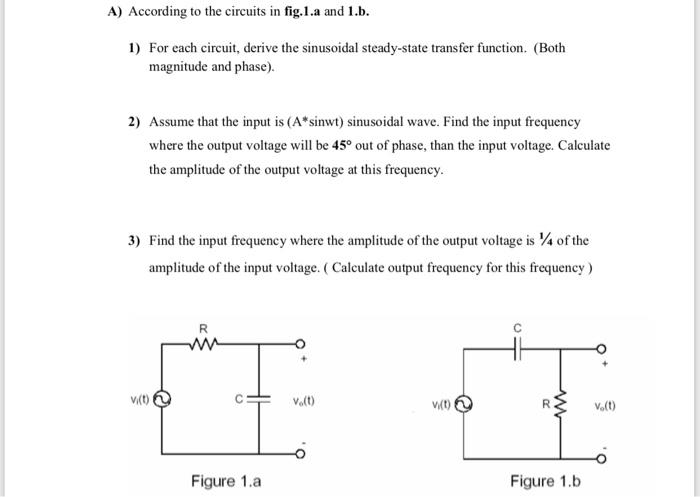
A) According to the circuits in fig.1.a and 1.b. 1) For each circuit, derive the sinusoidal steady-state transfer function. (Both magnitude and phase). 2)

A) According to the circuits in fig.1.a and 1.b. 1) For each circuit, derive the sinusoidal steady-state transfer function. (Both magnitude and phase). 2) Assume that the input is (A*sinwt) sinusoidal wave. Find the input frequency where the output voltage will be 45 out of phase, than the input voltage. Calculate the amplitude of the output voltage at this frequency. 3) Find the input frequency where the amplitude of the output voltage is 4 of the amplitude of the input voltage. ( Calculate output frequency for this frequency) Velt) Vt) V.(t) Figure 1.a Figure 1.b
Step by Step Solution
★★★★★
3.42 Rating (152 Votes )
There are 3 Steps involved in it
Step: 1

Get Instant Access to Expert-Tailored Solutions
See step-by-step solutions with expert insights and AI powered tools for academic success
Step: 2

Step: 3

Document Format ( 2 attachments)
635deb8d23ad8_179984.pdf
180 KBs PDF File
635deb8d23ad8_179984.docx
120 KBs Word File
Ace Your Homework with AI
Get the answers you need in no time with our AI-driven, step-by-step assistance
Get Started


