Question
At a minimum cover the following aspects: Positive and negative limiting load factor (i.e., the maximum G allowed for your aircraft) Stall speeds at 1,
At a minimum cover the following aspects:
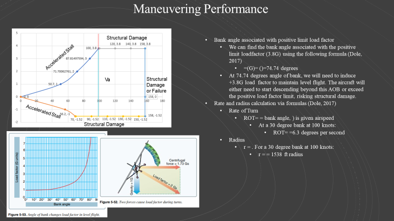
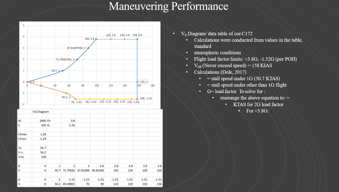
- Positive and negative limiting load factor (i.e., the maximum G allowed for your aircraft)
- Stall speeds at 1, 2, 3, and so on G up to the maximum positive G (at your selected weight)
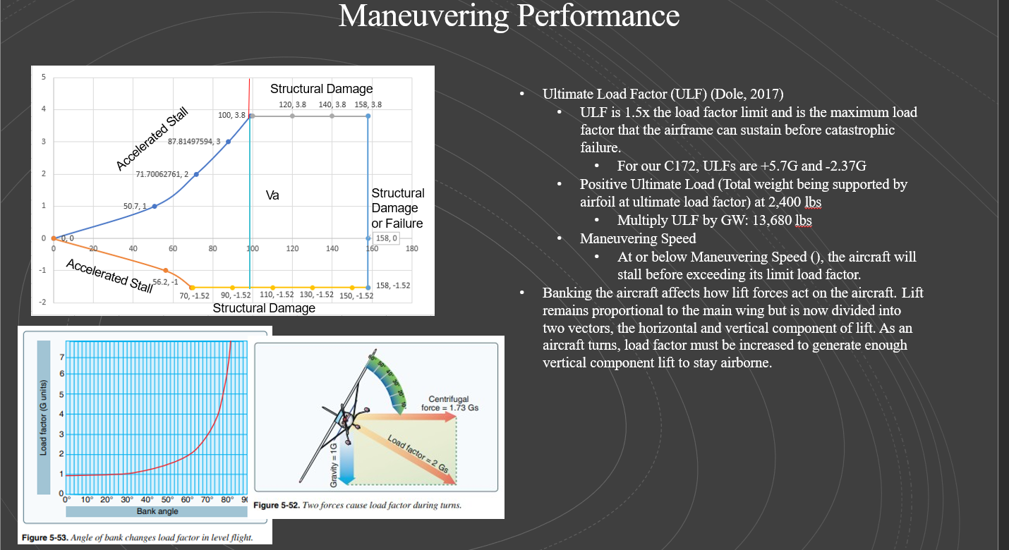
- Ultimate load factor (ULF)
- Positive ultimate load (i.e., the actual force [lbs]) at the selected weight
- Maneuvering speed
- The bank angle associated with the positive limiting load factor
- Rate and radius formula
- The turn performance diagram (Figure 2.29 in Aerodynamics for Naval Aviators, Hurt, 1965, p.179 or the Constant altitude turn performance diagram/figure in the textbook for in Chapter 11)
As in previous assignments, you will need to research a variety of additional information such as required formulas andpertinent aircraft data and/or assume a few parameters for your aircraft. Please make sure to detail those:
- Required Formulas:
- Bank angle to G relationship
- Turn rate and radius
- Stall speed under elevated G / bank
- Necessary aircraft information:
- Limiting load factors (positive and negative) for your example aircraft (from research)
- Assumed aircraft weight
- Previous information:
- Utilize your previous module work to find 1G stall speedfor your selected weight
- Assume atmospheric conditions
------------
*At a minimum cover the following aspects:
*Positive and negative limiting load factor (i.e., the maximum G allowed for your aircraft)
*Stall speeds at 1, 2, 3, and so on G up to the maximum positive G (at your selected weight)
*Ultimate load factor (ULF)
*Positive ultimate load (i.e., the actual force [lbs]) at the selected weight
*Maneuvering speed
*The bank angle associated with the positive limiting load factor
* For the specific maneuvering speedof your aircraft identified above,explain how to numerically find (provide thespecific example and values) the associated turn rate and radius utilizing both of the following methods:
*Rate and radius formula-So one slide is where you use the formula to determine Rate and Radius using the formulas-
*The next slide you will use the following turn performance diagram to determine Rate and Radius-show your work.
*Theturn performance diagram(Figure 2.29 in Aerodynamics for Naval Aviators, Hurt, 1965, p. 179 or Figure 13.14, Dole et al., 2017, p. 239)
*The bank angle associated with the positive limiting load factor
* As in previous assignments, you will need to research a variety of additional information such as required formulas andpertinent aircraft data and/or assume a few parameters for your aircraft. Please make sure to detail those:
*Required Formulas
*Bank angle to G relationship
*Turn rate and radius
*Stall speed under elevated G / bank
*Necessary aircraft information:
*Limiting load factors (positive and negative) for your example aircraft (from research)
*Assumed aircraft weight
*Previous information:
*Utilize your previous module work to find 1G stall speedfor your selected weight
*Assume atmospheric conditions-
------------------
How do you use this chart?
What is the formula to find maneuvering speed and what is that speed?
You needed to provide the answers


Step by Step Solution
There are 3 Steps involved in it
Step: 1

Get Instant Access to Expert-Tailored Solutions
See step-by-step solutions with expert insights and AI powered tools for academic success
Step: 2

Step: 3

Ace Your Homework with AI
Get the answers you need in no time with our AI-driven, step-by-step assistance
Get Started


