Answered step by step
Verified Expert Solution
Question
1 Approved Answer
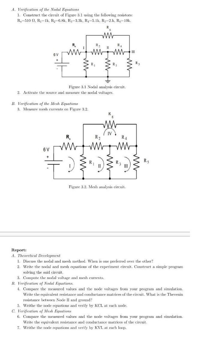
A. Verification of the Nodal Equations 1. Construct the circuit of Figure 3.1 using the following resistors: Ro-510 92, R-1k, R-6.8k, R3-3.3k, R-5.1k, R-2.k,

A. Verification of the Nodal Equations 1. Construct the circuit of Figure 3.1 using the following resistors: Ro-510 92, R-1k, R-6.8k, R3-3.3k, R-5.1k, R-2.k, R6-10k. R 6 V R www 6 V + B. Verification of the Mesh Equations 3. Measure mesh currents on Figure 3.2. R R www R 2. Activate the source and measure the nodal voltages. Figure 3.1 Nodal analysis circuit. R II R R II R R4 R3 III Figure 3.2. Mesh analysis circuit. III R R5 Report: A. Theoretical Development 1. Discuss the nodal and mesh method. When is one preferred over the other? 2. Write the nodal and mesh equations of the experiment circuit. Construct a simple programi solving the said circuit. 3. Compute the nodal voltage and mesh currents. B. Verification of Nodal Equations. 4. Compare the measured values and the node voltages from your program and simulation. Write the equivalent resistance and conductance matrices of the circuit. What is the Thevenin resistance between Node II and ground? 5. Writhe the node equations and verify by KCL at each node. C. Verification of Mesh Equations 6. Compare the measured values and the node voltages from your program and simulation. Write the equivalent resistance and conductance matrices of the circuit. 7. Writhe the node equations and verify by KVL at each loop.
Step by Step Solution
★★★★★
3.59 Rating (185 Votes )
There are 3 Steps involved in it
Step: 1
f 510 V 68 SIK write 051 6 051 my weite nodal at VI 61 NJ 68K 68 VV3 10 101 TO 2 w...
Get Instant Access to Expert-Tailored Solutions
See step-by-step solutions with expert insights and AI powered tools for academic success
Step: 2

Step: 3

Ace Your Homework with AI
Get the answers you need in no time with our AI-driven, step-by-step assistance
Get Started


