Answered step by step
Verified Expert Solution
Link Copied!

Question

1 Approved Answer

B4. Referring to the R-L circuit in Fig. B4, an inductor, with internal resistance R3=10, will be charged when the switch SW is closed at
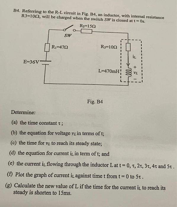
image text in transcribed
B4. Referring to the R-L circuit in Fig. B4, an inductor, with internal resistance R3=10, will be charged when the switch SW is closed at t=0 s. Fig. B4 Determine: (a) the time constant ; (b) the equation for voltage vL in terms of t; (c) the time for vL to reach its steady state; (d) the equation for current it in term of t; and (e) the current iL flowing through the inductor L at t=0,,2,3,4 and 5. (f) Plot the graph of current iL against time t from t=0 to 5. (g) Calculate the new value of L if the time for the current is to reach its steady is shorten to 15ms

Step by Step Solution

There are 3 Steps involved in it

Step: 1

blur-text-image

Get Instant Access to Expert-Tailored Solutions

See step-by-step solutions with expert insights and AI powered tools for academic success

Step: 2

blur-text-image

Step: 3

blur-text-image

Ace Your Homework with AI

Get the answers you need in no time with our AI-driven, step-by-step assistance

Get Started

Recommended Textbook for

Mass And Heat Transfer Analysis Of Mass Contactors And Heat Exchangers

Authors: T. W. Fraser Russell, Anne Skaja Robinson, Norman J. Wagner

1st Edition

0521886708, 9780521886703

More Books

Students also viewed these Chemical Engineering questions