Question: Basic Principles of Reection and Refraction There are two phenomena that occur when a light beam hits an interface between two different kinds of material:
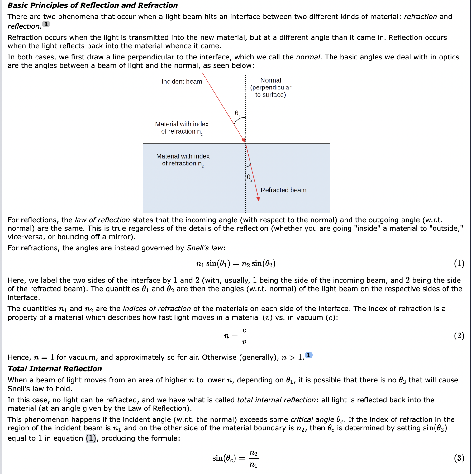
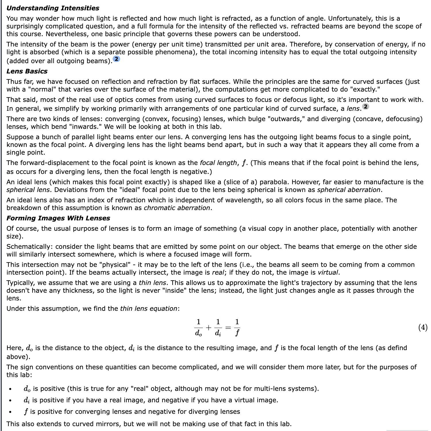
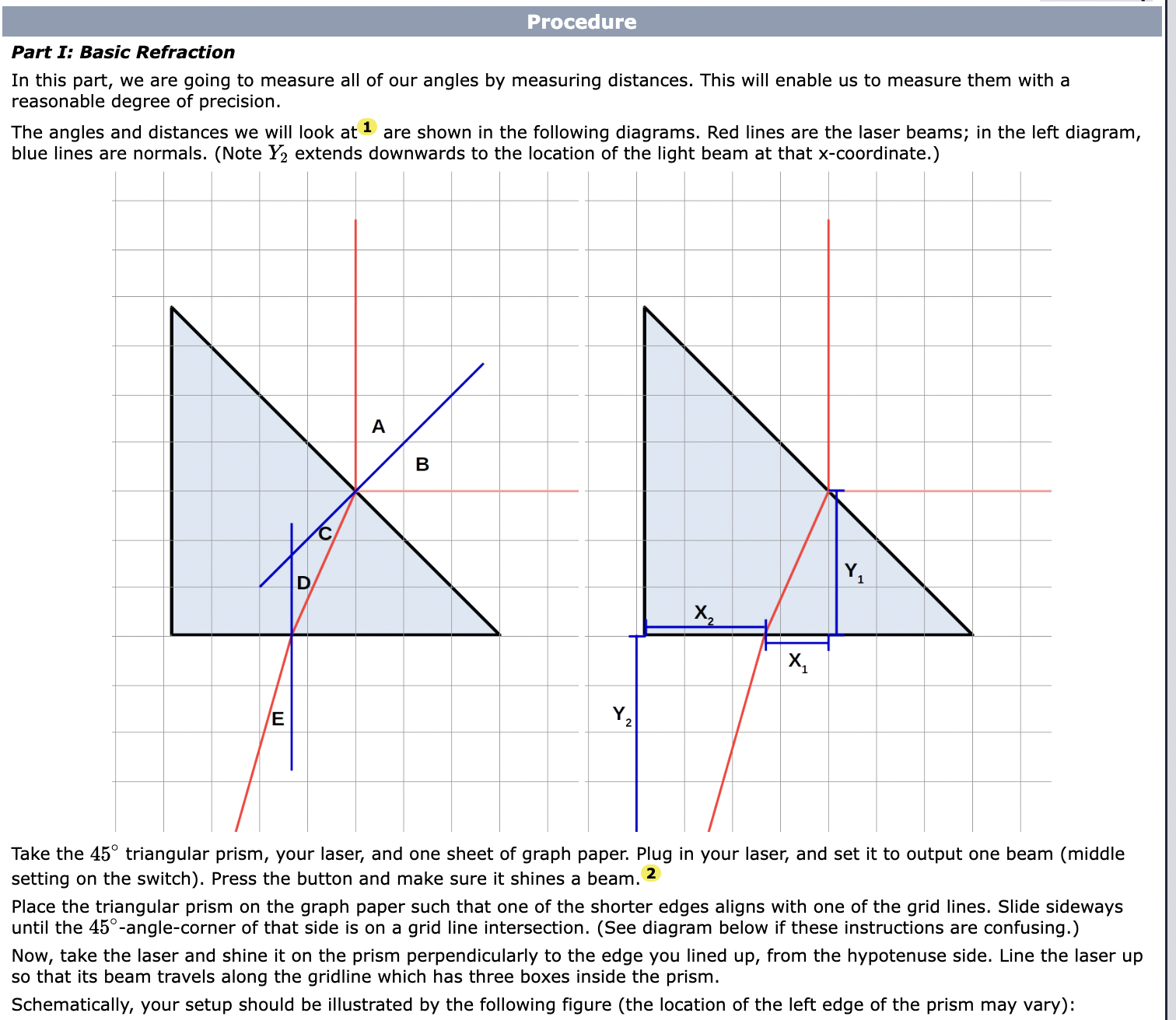
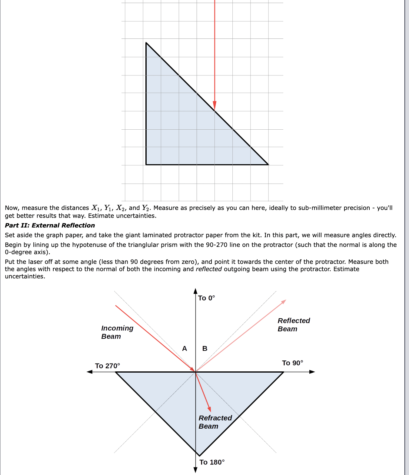
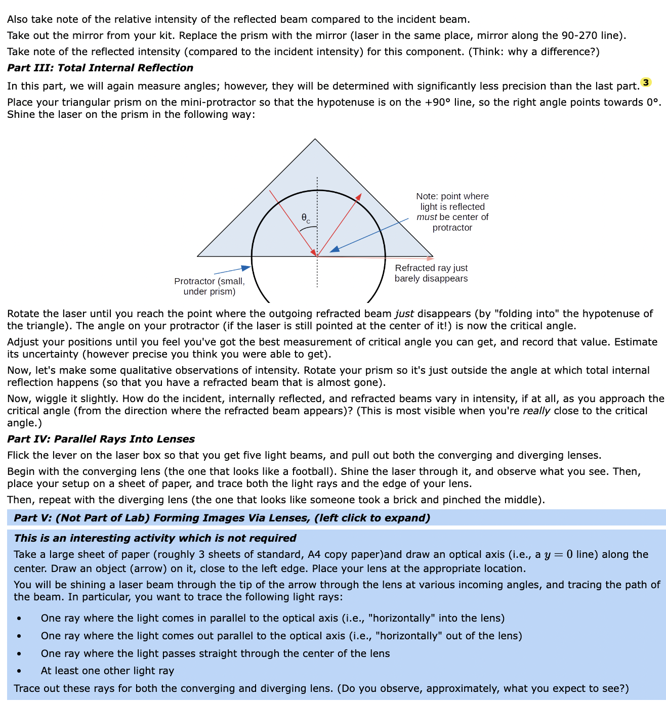
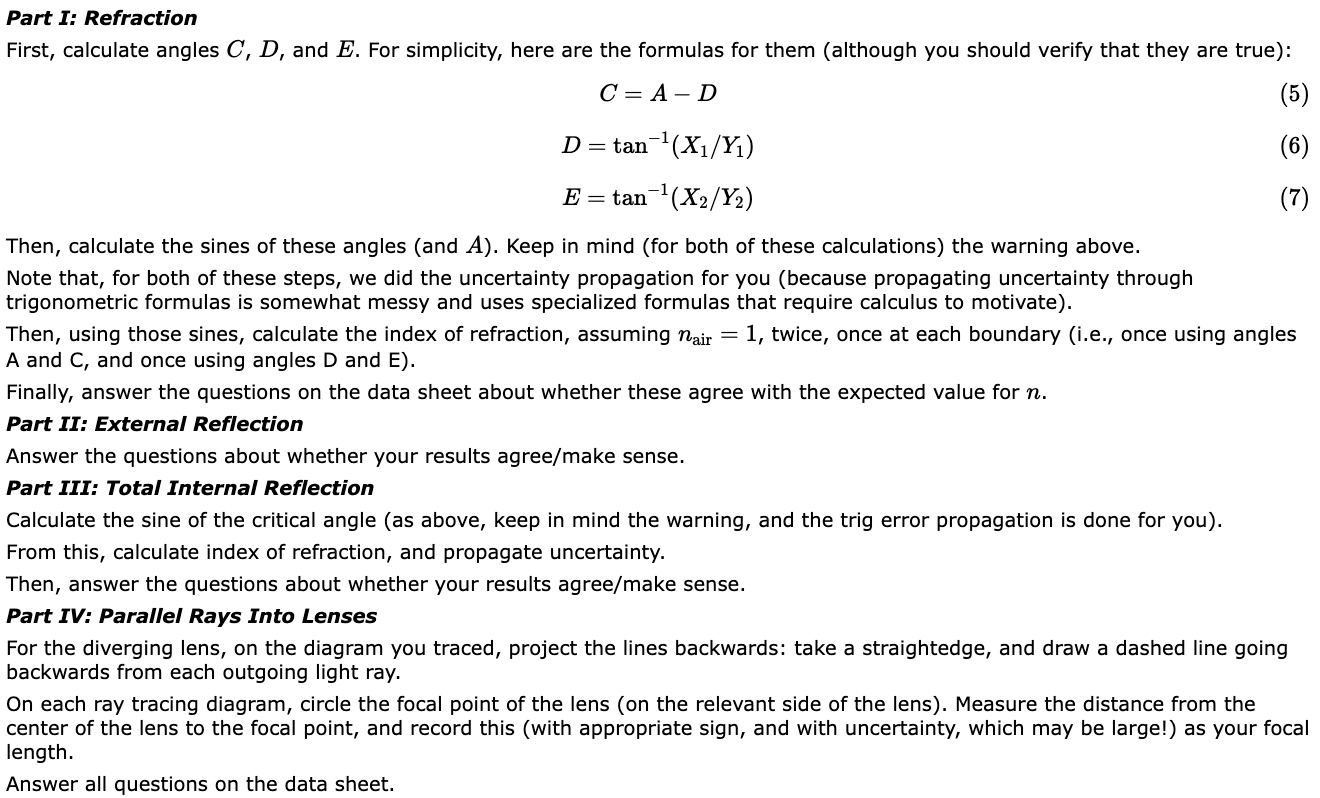
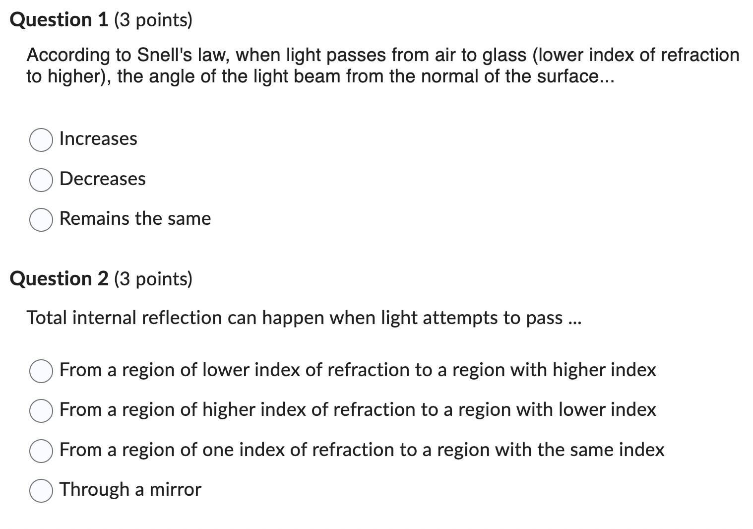
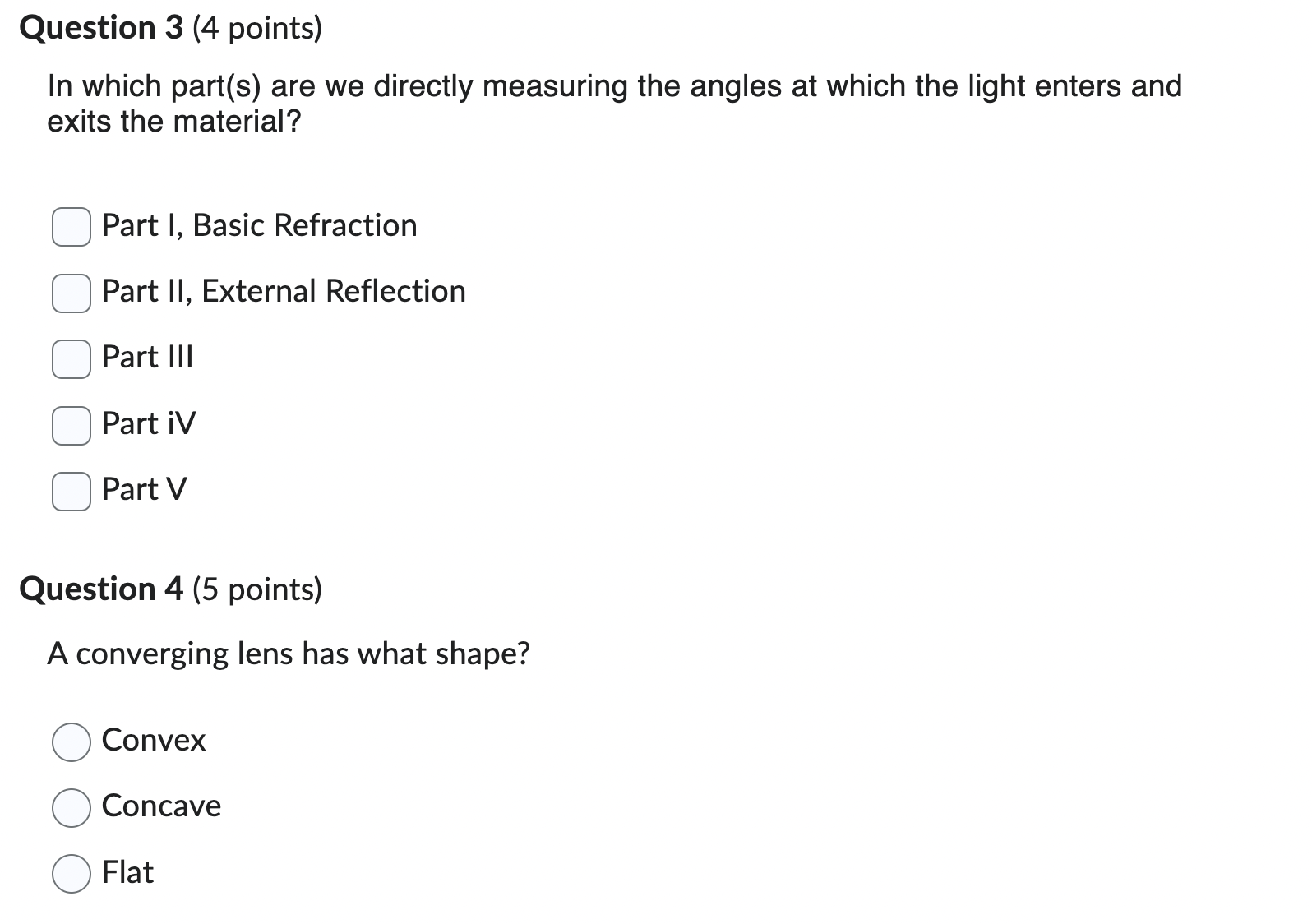
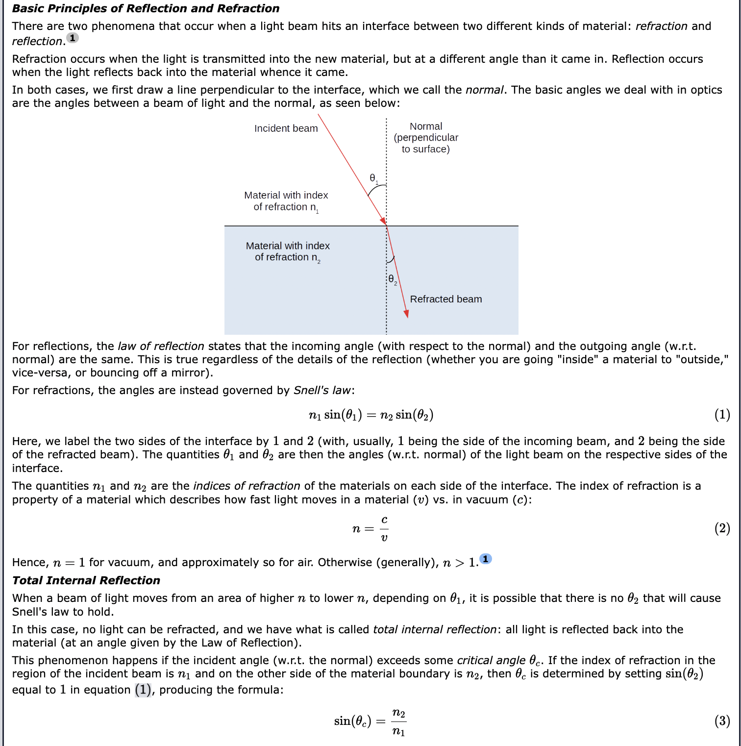
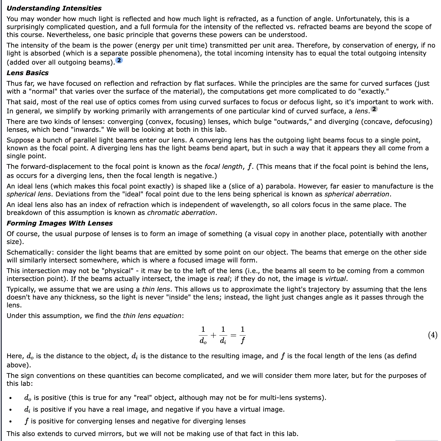
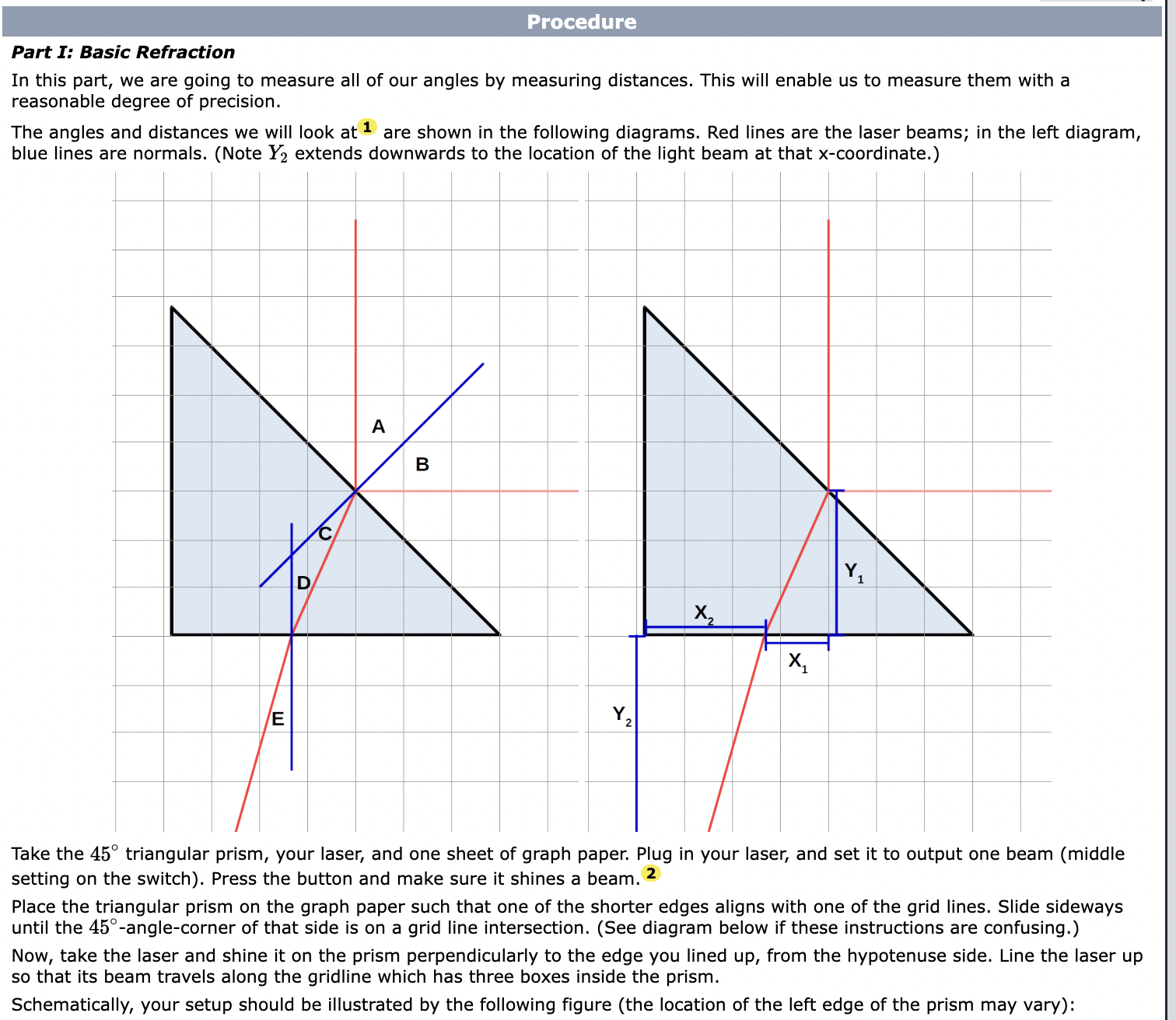
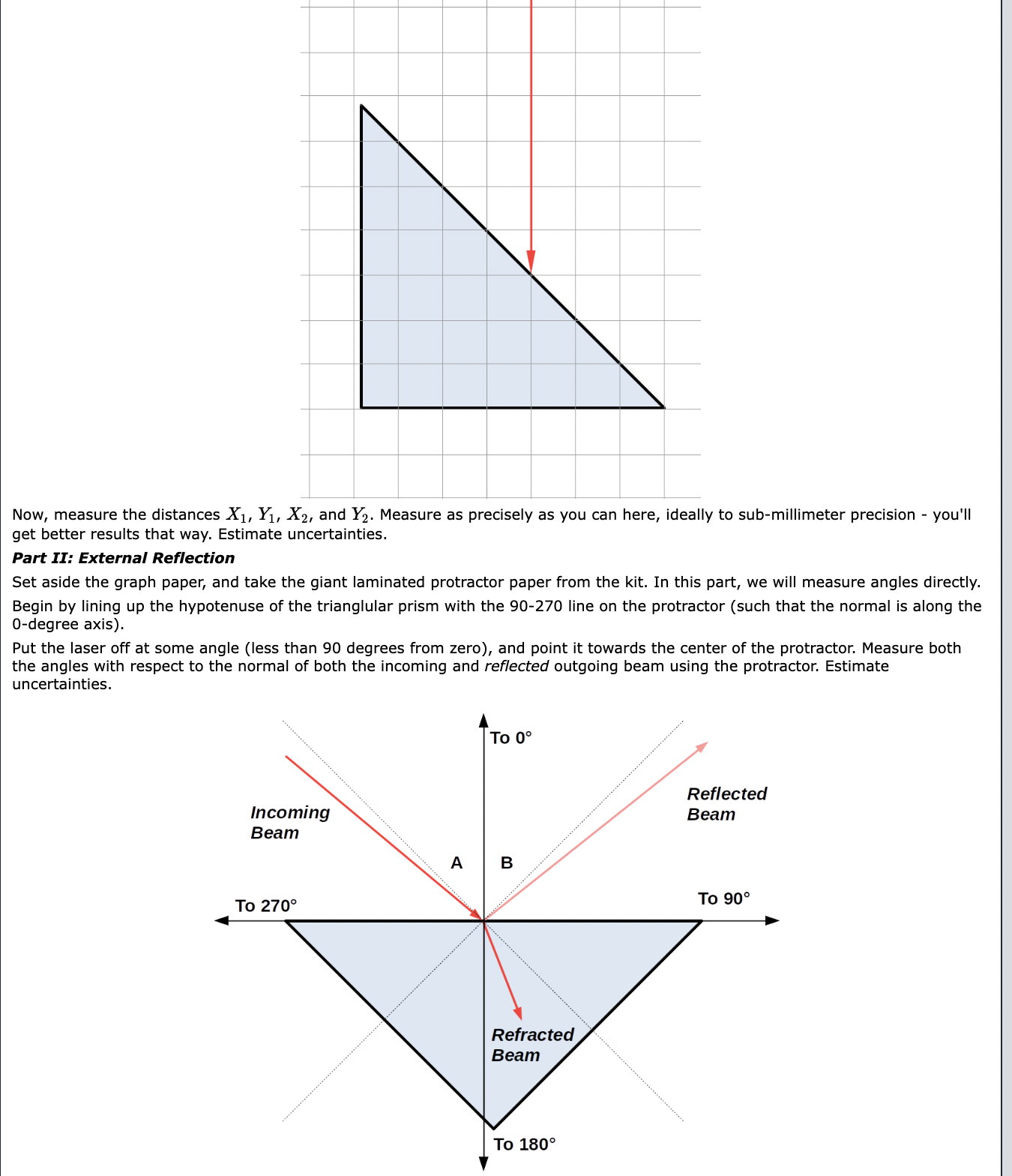
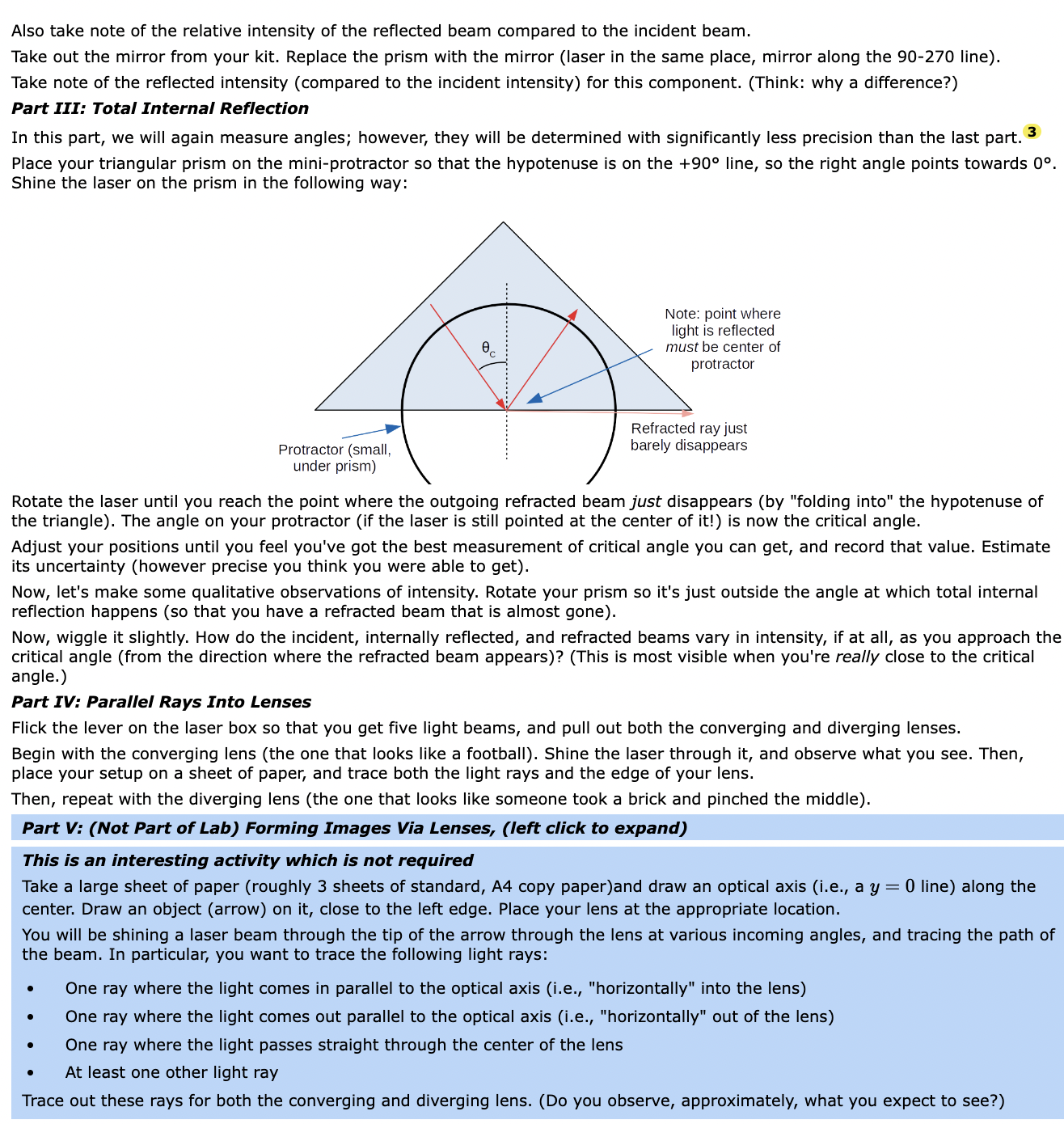
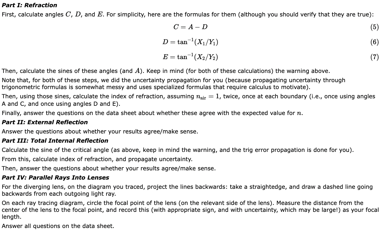
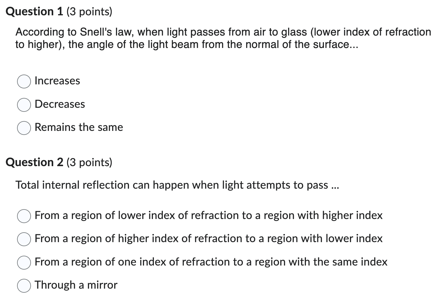
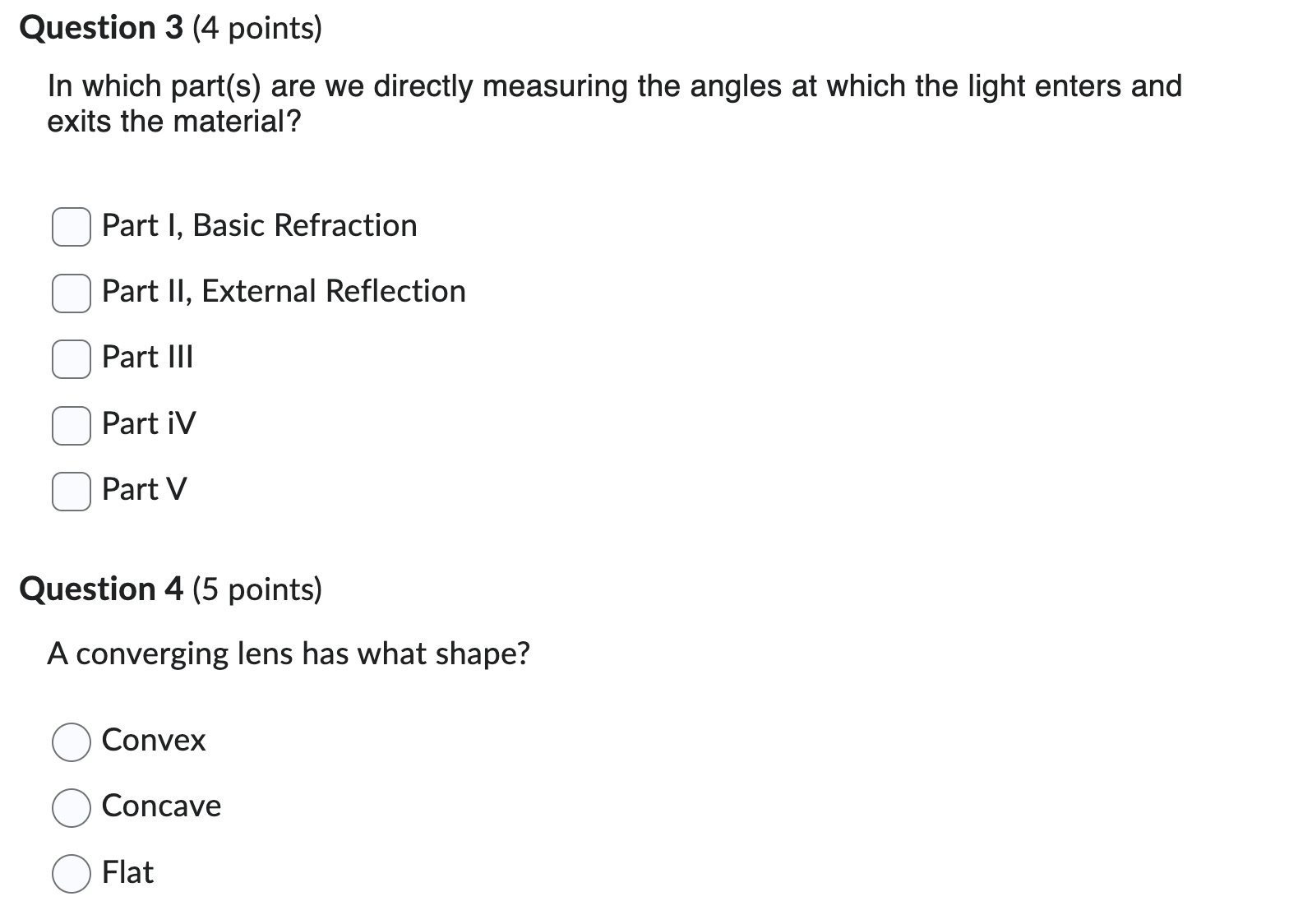
Basic Principles of Reection and Refraction There are two phenomena that occur when a light beam hits an interface between two different kinds of material: refraction and reection. '- Refraction Occurs when the light is transmitted into the new material, but at a different angle than it came in. Reflection occurs when the light reflects back into the material whence it came. In both cases, we rst draw a line perpendicular to the interface, which we call the normal. The basic angles we deal with in optics are the angles between a beam of light and the normal, as seen below: Incident beam Normal 3 (perpendicular to surface) Material With index of refraction n1 Material with index of refraction n2 Refracted beam For reflections, the law of reection states that the incoming angle (with respect to the normal) and the outgoing angle (w.r.t. normal) are the same. This is true regardless of the details of the reflection (whether you are going "inside" a material to "outside," vice-versa, or bouncing off a mirror). For refractions, the angles are instead governed by Snell's law: n1 5111(91) : n2 sin(92) (1) Here, we label the two sides of the interface by 1 and 2 (with, usually, 1 being the side of the incoming beam, and 2 being the side of the refracted beam). The quantities 91 and 92 are then the angles (w.r.t. normal) of the light beam on the respective sides of the interface. The quantities H1 and 71.2 are the indices of refraction of the materials on each side of the interface. The index of refraction is a property of a material which describes how fast light moves in a material (1:) vs. in vacuum (c): n2; (2) Hence, n : 1 for vacuum, and approximately so for air. Otherwise (generally), 11 > 1. 1 Total Internal Reection When a beam of light moves from an area of higher in to lower 11, depending on 91, it is possible that there is no 92 that will cause Snell's law to hold. In this case, no light can be refracted, and we have what is called total internal reection: all light is reflected back into the material (at an angle given by the Law of Reflection). This phenomenon happens if the incident angle (w.r.t. the normal) exceeds some critical angle 66. If the index of refraction in the region of the incident beam is in and on the other side of the material boundary is n2, then 9,: is determined by setting 5111092) equal to 1 in equation (1), producing the formula: n2 sin(6'c) : 7 (3) 1'11 Understanding Intensities You may wonder how much light is reflected and how much light is refracted, as a function of angle. Unfortunately, this is a surprisingly complicated question, and a full formula for the intensity of the reflected vs. refracted beams are beyond the scope of this course. Nevertheless, one basic principle that governs these powers can be understood. The intensity of the beam is the power (energy per unit time) transmitted per unit area. Therefore, by conservation of energy, if no light is absorbed (which is a separate possible phenomena), the total incoming intensity has to equal the total outgoing intensity (added over all outgoing beams). 2 Lens Basics Thus far, we have focused on reflection and refraction by flat surfaces. While the principles are the same for curved surfaces (just with a "normal" that varies over the surface of the material), the computations get more complicated to do "exactly." That said, most of the real use of optics comes from using curved surfaces to focus or defocus light, so it's important to work with. In general, we simplify by working primarily with arrangements of one particular kind of curved surface, a lens. 2 There are two kinds of lenses: converging (convex, focusing) lenses, which bulge "outwards," and diverging (concave, defocusing) lenses, which bend "inwards." We will be looking at both in this lab. Suppose a bunch of parallel light beams enter our lens. A converging lens has the outgoing light beams focus to a single point, known as the focal point. A diverging lens has the light beams bend apart, but in such a way that it appears they all come from a single point. The forward-displacement to the focal point is known as the focal length, f. (This means that if the focal point is behind the lens, as occurs for a diverging lens, then the focal length is negative.) An ideal lens (which makes this focal point exactly) is shaped like a (slice of a) parabola. However, far easier to manufacture is the spherical lens. Deviations from the "ideal'I focal point due to the lens being spherical is known as spherical aberration. An ideal lens also has an index of refraction which is independent of wavelength, so all colors focus in the same place. The breakdown of this assumption is known as chromatic aberration. Forming Images With Lenses Of course, the usual purpose of lenses is to form an image of something (a visual copy in another place, potentially with another size). Schematically: consider the light beams that are emitted by some point on our object. The beams that emerge on the other side will similarly intersect somewhere, which is where a focused image will form. This intersection may not be "physical" - it may be to the left of the lens (i.e., the beams all seem to be coming from a common intersection point). If the beams actually intersect, the image is real, if they do not, the image is virtual. Typically, we assume that we are using a thin lens. This allows us to approximate the light's trajectory by assuming that the lens doesn't have any thickness, so the light is never "inside" the lens; instead, the light just changes angle as it passes through the lens. Under this assumption, we nd the thin lens equation: 1 1 1 i:i 4 did.- f U Here, (1,, is the distance to the object, (ii is the distance to the resulting image, and f is the focal length of the lens (as dend above). The sign conventions on these quantities can become complicated, and we will consider them more later, but for the purposes of this lab: - do is positive (this is true for any "real" object, although may not be for multi-lens systems). . d,- is positive if you have a real image, and negative if you have a virtual image. . f is positive for converging lenses and negative for diverging lenses This also extends to curved mirrors, but we will not be making use of that fact in this lab. Procedure Part I: Basic Refraction In this part, we are going to measure all of our angles by measuring distances. This will enable us to measure them with a reasonable degree of precision. The angles and distances we will look at 1 are shown in the following diagrams. Red lines are the laser beams; in the left diagram, blue lines are normals. (Note Y2 extends downwards to the location of the light beam at that xcoordinate.) Take the 45 triangular prism, your laser, and one sheet of graph paper. Plug in your laser, and set it to output one beam (middle setting on the switch). Press the button and make sure it shines a beam. 2 Place the triangular prism on the graph paper such that one of the shorter edges aligns with one of the grid lines. Slide sideways until the 45-anglecorner of that side is on a grid line intersection. (See diagram below if these instructions are confusing.) Now, take the laser and shine it on the prism perpendicularly to the edge you lined up, from the hypotenuse side. Line the laser up so that its beam travels along the gridline which has three boxes inside the prism. Schematically, your setup should be illustrated by the following figure (the location of the left edge of the prism may vary): Now, measure the distances X1, Y1, X2, and Y2. Measure as precisely as you can here, ideally to sub-millimeter precision - you'll get better results that way. Estimate uncertainties. Part II: External Reflection Set aside the graph paper, and take the giant laminated protractor paper from the kit. In this part, we will measure angles directly. Begin by lining up the hypotenuse of the trianglular prism with the 90-270 line on the protractor (such that the normal is along the O-degree axis). Put the laser off at some angle (less than 90 degrees from zero), and point it towards the center of the protractor. Measure both the angles with respect to the normal of both the incoming and reected outgoing beam using the protractor. Estimate uncertainties. To 0 Reflected incoming Beam Beam Refracted Also take note of the relative intensity of the reected beam compared to the incident beam. Take out the mirror from your kit. Replace the prism with the mirror (laser in the same place, mirror along the 90-270 line). Take note of the reflected intensity (compared to the incident intensity) for this component. (Think: why a difference?) Part III: Total Internal Reflection In this part, we will again measure angles; however, they will be determined with significantly less precision than the last part. 3 Place your triangular prism on the mini-protractor so that the hypotenuse is on the +90" line, so the right angle points towards 0. Shine the laser on the prism in the following way: Note: pointwhere light is reflected must be center of protractor -_-I' _,_F~ Protractor (small. under prism) Refracled ray just barely disappears Rotate the laser until you reach the point where the outgoing refracted beam just disappears (by "folding into" the hypotenuse of the triangle). The angle on your protractor (if the laser is still pointed at the center of it!) is now the critical angle. Adjust your positions until you feel you've got the best measurement of critical angle you can get, and record that value. Estimate its uncertainty (however precise you think you were able to get). Now, let's make some qualitative observations of intensity. Rotate your prism so it's just outside the angle at which total internal reection happens {so that you have a refracted beam that is almost gone). Now, wiggle it slightly. How do the incident, internally reflected, and refracted beams vary in intensity, if at all, as you approach the critical angle (from the direction where the refracted beam appears)? (This is most visible when you're really close to the critical angle.) Part IV: Parallel Rays Into Lenses Flick the lever on the laser box so that you get five light beams, and pull out both the converging and diverging lenses. Begin with the converging lens (the one that looks like a football). Shine the laser through it, and observe what you see. Then, place your setup on a sheet of paper, and trace both the light rays and the edge of your lens. Then, repeat with the diverging lens {the one that looks like someone took a brick and pinched the middle). Part 1/: (Not Part of Lab) Forming Images Via Lenses, (left click to expand) This is an interesting activity which is not required Take a large sheet of paper (roughly 3 sheets of standard, A4 copy paper)and draw an optical axis (i.e., a y = 0 line) along the center. Draw an object (arrow) on it, close to the left edge. Place your lens at the appropriate location. You will be shining a laser beam through the tip of the arrow through the lens at various incoming angles, and tracing the path of the beam. In particular, you want to trace the following light rays: - One ray where the light comes in parallel to the optical axis (i.e., "horizontally" into the lens) - One ray where the light comes out parallel to the optical axis (i.e., "horizontally" out of the lens) - One ray where the light passes straight through the center of the lens I At least one other light ray Trace out these rays for both the converging and diverging lens. (Do you observe, approximately, what you expect to see?) Part I: Refraction First, calculate angles C, D, and E. For simplicity, here are the formulas for them (although you should verify that they are true): 0 : A _ D (5) D : tan1(X1/Y1) (6) E : tan1(X2/Y2) (7) Then, calculate the sines of these angles (and A). Keep in mind (for both of these calculations) the warning above. Note that, for both of these steps, we did the uncertainty propagation for you (because propagating uncertainty through trigonometric formulas is somewhat messy and uses specialized formulas that require calculus to motivate}. Then, using those sines, calculate the index of refraction, assuming nah = 1, twice, once at each boundary (i.e., once using angles A and C, and once using angles D and E). Finally, answer the questions on the data sheet about whether these agree with the expected value for in. Part II: External Reflection Answer the questions about whether your results agree/make sense. Part III: Total Internal Reflection Calculate the sine of the critical angle (as above, keep in mind the warning, and the trig error propagation is done for you). From this, calculate index of refraction, and propagate uncertainty. Then, answer the questions about whether your results agree/make sense. Part IV: Parallel Rays Into Lenses For the diverging lens, on the diagram you traced, project the lines backwards: take a straightedge, and draw a dashed line going backwards from each outgoing light ray. On each ray tracing diagram, circle the focal point of the lens (on the relevant side of the lens). Measure the distance from the center of the lens to the focal point, and record this (with appropriate sign, and with uncertainty, which may be large!) as your focal length. Answer all questions on the data sheet. Question 1 (3 points) According to Snell's law, when light passes from air to glass (lower index of refraction to higher), the angle of the light beam from the normal of the surface... 0 Increases O Decreases O Remains the same Question 2 (3 points) Total internal reflection can happen when light attempts to pass O From a region of lower index of refraction to a region with higher index 0 From a region of higher index of refraction to a region with lower index 0 From a region of one index of refraction to a region with the same index 0 Through a mirror Question 3 (4 points) In which part(s) are we directly measuring the angles at which the light enters and exits the material? [3 Part I, Basic Refraction D Part II, External Reflection Question 4 (5 points) A converging lens has what shape? 0 Convex O Concave Q Flat
Step by Step Solution
There are 3 Steps involved in it

Get step-by-step solutions from verified subject matter experts


