Answered step by step
Verified Expert Solution
Question
1 Approved Answer
Bernoulli Equation Lab Experiment Principle of the Lab Under the assumption of steady, incompressible, inviscid flow in a gravitational field, the Bernoulli equation, V


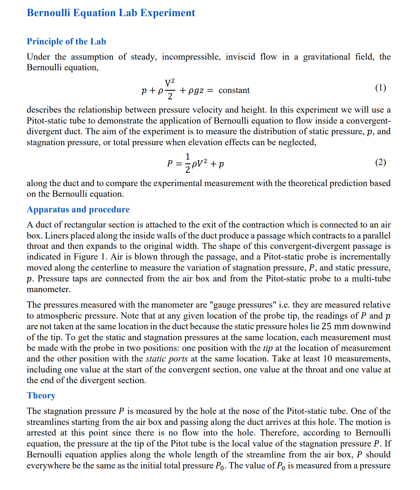
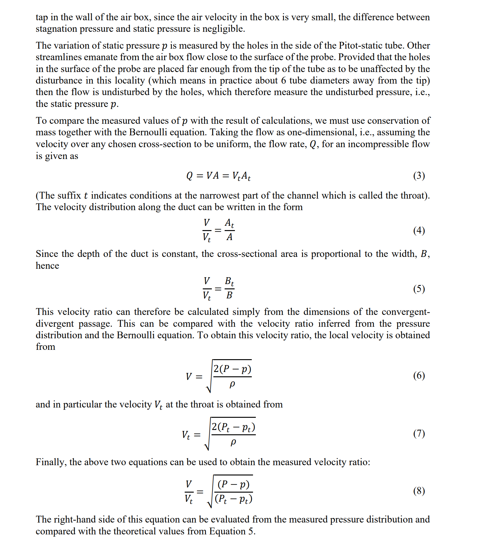
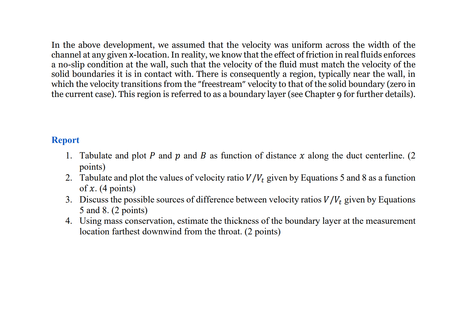
Bernoulli Equation Lab Experiment Principle of the Lab Under the assumption of steady, incompressible, inviscid flow in a gravitational field, the Bernoulli equation, V p+PZ +pgz = constant (1) describes the relationship between pressure velocity and height. In this experiment we will use a Pitot-static tube to demonstrate the application of Bernoulli equation to flow inside a convergent- divergent duct. The aim of the experiment is to measure the distribution of static pressure, p, and stagnation pressure, or total pressure when elevation effects can be neglected, 1 P === pv + + p (2) along the duct and to compare the experimental measurement with the theoretical prediction based on the Bernoulli equation. Apparatus and procedure A duct of rectangular section is attached to the exit of the contraction which is connected to an air box. Liners placed along the inside walls of the duct produce a passage which contracts to a parallel throat and then expands to the original width. The shape of this convergent-divergent passage is indicated in Figure 1. Air is blown through the passage, and a Pitot-static probe is incrementally moved along the centerline to measure the variation of stagnation pressure, P, and static pressure, p. Pressure taps are connected from the air box and from the Pitot-static probe to a multi-tube manometer. The pressures measured with the manometer are "gauge pressures" i.e. they are measured relative to atmospheric pressure. Note that at any given location of the probe tip, the readings of P and p are not taken at the same location in the duct because the static pressure holes lie 25 mm downwind of the tip. To get the static and stagnation pressures at the same location, each measurement must be made with the probe in two positions: one position with the tip at the location of measurement and the other position with the static ports at the same location. Take at least 10 measurements, including one value at the start of the convergent section, one value at the throat and one value at the end of the divergent section. Theory The stagnation pressure P is measured by the hole at the nose of the Pitot-static tube. One of the streamlines starting from the air box and passing along the duct arrives at this hole. The motion is arrested at this point since there is no flow into the hole. Therefore, according to Bernoulli equation, the pressure at the tip of the Pitot tube is the local value of the stagnation pressure P. If Bernoulli equation applies along the whole length of the streamline from the air box, P should everywhere be the same as the initial total pressure Po. The value of Po is measured from a pressure tap in the wall of the air box, since the air velocity in the box is very small, the difference between stagnation pressure and static pressure is negligible. The variation of static pressure p is measured by the holes in the side of the Pitot-static tube. Other streamlines emanate from the air box flow close to the surface of the probe. Provided that the holes in the surface of the probe are placed far enough from the tip of the tube as to be unaffected by the disturbance in this locality (which means in practice about 6 tube diameters away from the tip) then the flow is undisturbed by the holes, which therefore measure the undisturbed pressure, i.e., the static pressure p. To compare the measured values of p with the result of calculations, we must use conservation of mass together with the Bernoulli equation. Taking the flow as one-dimensional, i.e., assuming the velocity over any chosen cross-section to be uniform, the flow rate, Q, for an incompressible flow is given as Q = VA = VAt (3) (The suffix t indicates conditions at the narrowest part of the channel which is called the throat). The velocity distribution along the duct can be written in the form V Vt = At A (4) Since the depth of the duct is constant, the cross-sectional area is proportional to the width, B, hence V Vt Bt B (5) This velocity ratio can therefore be calculated simply from the dimensions of the convergent- divergent passage. This can be compared with the velocity ratio inferred from the pressure distribution and the Bernoulli equation. To obtain this velocity ratio, the local velocity is obtained from 2(P - p) V = and in particular the velocity Vt at the throat is obtained from 2(Pt - Pt) V = P Finally, the above two equations can be used to obtain the measured velocity ratio: V Vt = (P - p) (Pt - Pt) (6) (7) (8) The right-hand side of this equation can be evaluated from the measured pressure distribution and compared with the theoretical values from Equation 5. In the above development, we assumed that the velocity was uniform across the width of the channel at any given x-location. In reality, we know that the effect of friction in real fluids enforces a no-slip condition at the wall, such that the velocity of the fluid must match the velocity of the solid boundaries it is in contact with. There is consequently a region, typically near the wall, in which the velocity transitions from the "freestream" velocity to that of the solid boundary (zero in the current case). This region is referred to as a boundary layer (see Chapter 9 for further details). Report 1. Tabulate and plot P and p and B as function of distance x along the duct centerline. (2 points) 2. Tabulate and plot the values of velocity ratio V/Vt given by Equations 5 and 8 as a function of x. (4 points) 3. Discuss the possible sources of difference between velocity ratios V/Vt given by Equations 5 and 8. (2 points) 4. Using mass conservation, estimate the thickness of the boundary layer at the measurement location farthest downwind from the throat. (2 points)
Step by Step Solution
There are 3 Steps involved in it
Step: 1

Get Instant Access to Expert-Tailored Solutions
See step-by-step solutions with expert insights and AI powered tools for academic success
Step: 2

Step: 3

Ace Your Homework with AI
Get the answers you need in no time with our AI-driven, step-by-step assistance
Get Started


