Question: BON - 5 cm TON : 7 cm 10ON , 10 cm BON - 8cm 6 10 rim 7 CM 4.50 Som 180 270 Fix


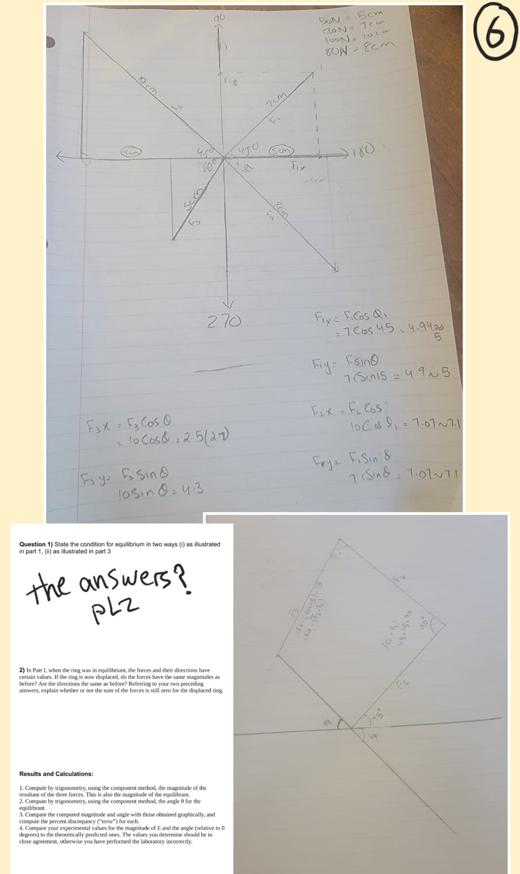
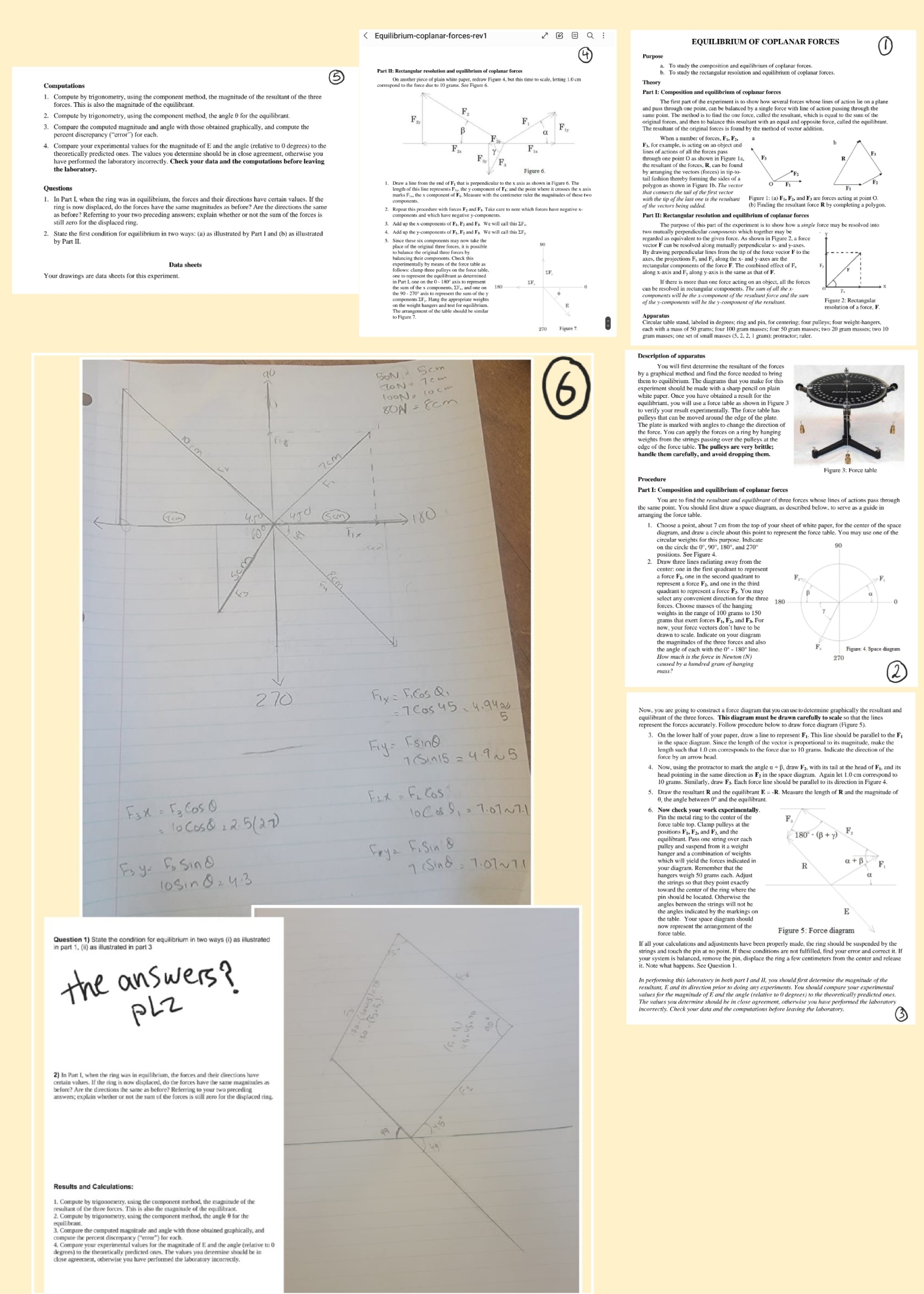
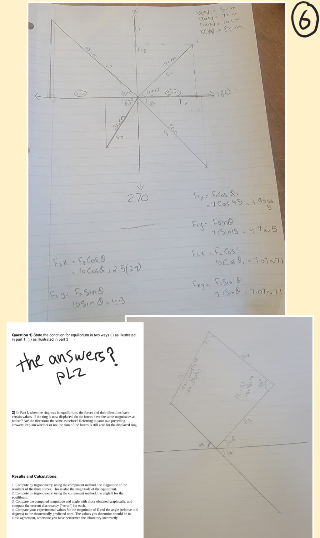
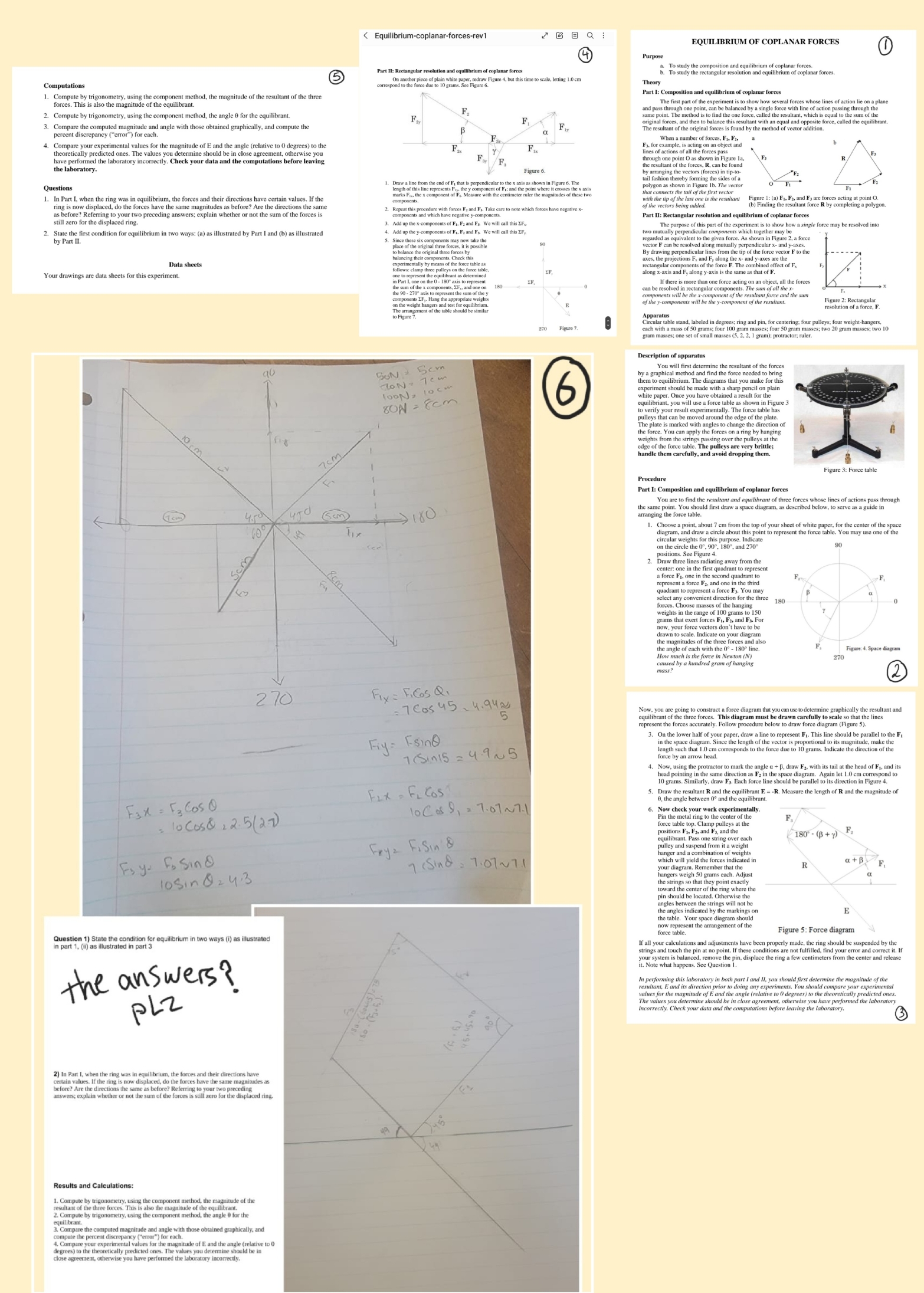
BON - 5 cm TON : 7 cm 10ON , 10 cm BON - 8cm 6 10 rim 7 CM 4.50 Som 180 270 Fix = FiGos Q, = 7 Cos 45 - 4.94 N 5 Fry = Fsino 7 ( Sin15 = 4.9 ~5 Fax = F 3 Cos 0 Fix = FL COS = 10 Cos& 2 2.5 (27) 10 Cos $1 = 7.07 ~7.1 Foy. Fo Sind Fry = FiSin 8 10sin Q 2 4:3 7 ( Sing - 7.07 ~71 Question 1) State the condition for equilibrium in two ways (1) as illustrated in part 1, (ii) as illustrated in part 3 the answers ? PLZ So- ( 60LHS ) 9 75 150 . (F + 6 ) . 15+4590 2) In Part 1, when the ring was in equilibrium, the forces and their directions have certain values. If the ring is now displaced, do the forces have the same magnitudes as before? Are the directions the same as before? Referring to your two preceding answers; explain whether or not the sum of the forces is still zero for the displaced ring. Results and Calculations: 1. Compute by trigonometry, using the component method, the magnitude of the resultant of the three forces. This is also the magnitude of the equilibrant. equilibrant. 2. Compute by trigonometry, using the component method, the angle 0 for the 3. Compare the computed magnitude and angle with those obtained graphically, and compute the percent discrepancy ("error") for each. 4. Compare your experimental values for the magnitude of E and the angle (relative to 0 degrees) to the theoretically predicted ones. The values you determine should be in close agreement, otherwise you have performed the laboratory incorrectly.Equilibrium-coplanar-forces-rev1 EQUILIBRIUM OF COPLANAR FORCES Purpose study the composition and equilibrium of coplanar forces. (5 Part II: Rectangular resolution and equilibrium of coplanar forces b. To study the rectangular resolution and equilibrium of coplanar forces. Computations rrespond to the force due to 10 grams. See Figure 6. Compute by trigonometry, using the component method, the magnitude of the resultant of the three Part I: Composition and equilibrium of coplanar forces de of the equilibrant. The first part of the experiment is to show how several forces whose lines of action 2. Compute by trigonometry, using the component method, the angle 0 for the equilibrant pass through one point, can be balanced by a single force with line of action passing through the Compare the computed magnitude and angle with those obtained graphically, and compute the final forces, and then to balance this resultant with an equal and opposite force, called the equilibran com discrepancy ("error") for each. The resultant of the original forces is found by the method of vector addition. When a number of forces, F1, Fa. 4. Compare your experimental vanties for the magnitude of to the me angle (relative to 0 degrees) to the F. F.. have performed the laboratory incorrectly. Check your data and the computations before leaving F. mes of actions of all the forces pass the laboratory. F. Figure 6 he resultant of the forces, R, can be found Draw a line from the end of Fi that is perpendicular to the x axis as shown in Figure 6. The ail fashion thereby forming the sides of a Questions marks Fo.. the s componem of F . . Measure with the centimeter ruler the magnitudes of these polygon as shown in Figure 16. The vector a Part I when the ring was in equiforum, the forces and their affection, hive certain values, if the of the vectors the rest of as before? Referring to your two preceding answers: explain whether or not the sum of the forces is berge genes and whewhamas and Fi. Take care to note ( b) Finding the resultant force R by completing a polygon still zero for the displaced ring. Part II: Rectangular resol 3. Add up the x-components of F). F; and Fx We will call this EF,. ectangular resolution and equilibrium of coplanar forces State the first condition for equilibrium in two ways: (a) as illustrated by Part I and (b) as illustrated 4. Add up the y-components of F1, Fa and Fy We will call this IF, The purpose of this part of the experiment is to show how a single force may be resolved into by Part II. two mutually perpendicular components which together may be "place of the original three forces, it is possible rector F can be resolved alone munaany perenni megaforce Data sheets balancing their components. Check this xes. the projections F. and Fy along the x- and y-ases are the Experimentally by means of the force table as Your drawings are data sheets for this experiment. one to represent the equilibrant as determined long x-axis and Fy along y-axis is the same as that of F. the sum of the * components , IF., and one on If there is more than one force acting on an object, all the forces the 90 - 270 quis to represent the sum of the y can be resolved in rectangular components. The sum of all the s of the y-components will be the y-component of the resultant. Figure 2: Rectangular The arrangement of the table should be similar resolution of a force, Apparatus Figure 7. cach with the stands sheled in degrees. ring and pin, for centering: four pulleys: four werent-hansen gram masses; one set of small masses (5. 2. 2. I gram): protractor; ruler. Description of apparatus SON pod will first determine the resultant of the bites hem to equilibrium. The diagrams that you make for this 10ON = 10 cm white paper. Once you have obtained a result for the CON - 8cm equilibriant, you will use a force table as shown in Figure pulleys that can be moved around the edge of the plate. he force. You can apply the forces on a ring by hanging 10 km we'The force table. The pulleys are very him 7 CM handle them carefully, and avoid dropping them. Figure 3: Force table Procedure Part 1: Composition and equilibrium of coplanar forces You are to find the resultant and equilibrant of three forces whose lines of actions pass through 180 ranging the force should first draw a space diagram, as described below, to serve as a guide in . Choose a point, about 7 cm from the top of your sheet of white paper, for the center of the space diagram, and draw a circle about this point to represent the force table. You may use one of the 90 Som a force be. onete e wed ing in the third quadrant to represent a force F3. You may elect any convenient direction for the three 180 weights in the more of 100 arms to 150 grams that exert forces Fi, Fa, and Fx For drawn to scale. Indicate on your diagram the magnitudes of the three forces and also How much is the force in Newton ( NI 270 4. Space diagram caused by a hundred gram of hanging (2 1270 Fix = FiCos Q, : 7 Cos 45 - 4. 94 N 5 Now. you are going to construct a force diagram that you can use to determine graphically the resultant and cpresent the forces accurately. Follow procedure below to draw force diagram (Figure 5). Fry = Esind 3. On the lower half of your paper, draw a line to represent Fi. This line should be parallel to the F, 7 sin15 = 4.9 ~5 length such that 1.0 cm corresponds to the force due to 10 grams Indicate the direct force by an arrow 10 grams. Similarly, draw Es. Each force line should be parallel to its direction in Figure 4. FIX = FL Cos the whole between ge and ignorant & = - ibrant E - -R. Measure the length of R and the magnitude of Fax = F 3 Cos 0 10 Cos 9, = 7.07 ~7.1 Now check your work experimentally : 10 Cos& 2 2.5 ( 27) Pin the metal ring to the center of the F, Positions F 1 8 2, and F's, and the 180'- (B + y) Fry = FiSin 8 pulley and suspend from it a weight Foy- Fo sind 7 ( Sind : 7.07 ~71 which will yield the forces indicated in R a + B your diagram. Remember that the 10 sin 0 2 4.3 the strings so that they point exactly pin should he located one came angles between the strings will not be E the table. Your space diagram should arrangement of the Question 1) State the condition for eq part 1. (#) as illustrated in part 3 alibrium in two ways (1) as ilustrated Figure 5: Force diagram window touch the bills no point if these conditions are not fulfilled. find your error and correct it. I your system is balanced , remove the pin. displace the ring a few centimeters from the center and release the answers ? it. Note what happens. See Question . In performing this laboratory in both part I and II, you should first determine the magnitude of the values for the magnitude of F and the angie (relative to O degrees) to the theoretically predicted ones PLZ The values you determine should be in close agreement, otherwise you have performed the laboratory incorrectly. Check your data and the computations before leaving the laboratory. 50 . ( FJUG ) . ( 3 ) 45+45,90 ( F .B ) 2) In Part I, when the ring was in equilibrium, the forces and their directions have direction 's now displaced, do the forces have the same magmitte answers; explain whether or not the sum of the forces is still zero for the displaced ring. Results and Calculations: 1. Compute by trigonometry, using the component method, the magnitude of the 2. Compute by trigonomen This 3. Compare the computed magnitude and angle with those obtained graphically, and 4. Compare your experimental values for the magnitude of E and the angle (relative to O close agreement, otherwise you have performed the laboratory incorrectly
Step by Step Solution
There are 3 Steps involved in it

Get step-by-step solutions from verified subject matter experts


