

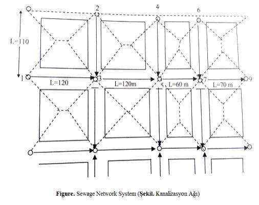
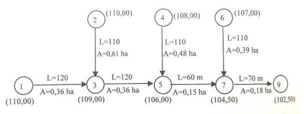
Question: By designing the 1-3 , 3-5 , 5-7, and 7-9 pipelines in the wastewater sewage system given in the figure, please form or draw a
By designing the 1-3, 3-5, 5-7, and 7-9 pipelines in the wastewater sewage system given in the figure, please form or draw a profile of this sewage system. Determine all the crest elevations and the pipeline base elevations. Since there is an industrial process at the beginning of the 2-3 pipeline, which is domestic wastewater and has a flow rate value of 1.3 L/s, analyze hydraulic calculations of the sewer pipeline. Other required values to be used in the calculations are shown below.
Maximum partially full ratio: h/D= 0.60 or 60%
Maximum daily water consumption: 300 L/P.day
Population density: a= 250 people or individual/hectares (ha)
Minimum pipeline diameter: Dmin=200 mm
Minimum pipeline depth : hmin=2.50 m
Maximum pipeline depth : hmax=5.50 m
Minimum pipeline slope : jmin=0.003
Maximum pipeline slope : jmax=0.07
Maximum drop height : Δh=2.50 m
Note : Kutter formula will be used for the calculations. The areas that supply water to the channels, will be calculated from the geometrical areas as seen in the figure above.
L=110 L=120 L=120m 4 5, L-60 m 6 Figure. Sewage Network System (ekil. Kanalizasyon A) L-70 m
Step by Step Solution
3.39 Rating (146 Votes )
There are 3 Steps involved in it

Get step-by-step solutions from verified subject matter experts