

Question
By using the Euler-Lagrange method, and considering g = 1 and q2 = 0 as generalised coordinates, the inverted pendulum system in Fig. 2
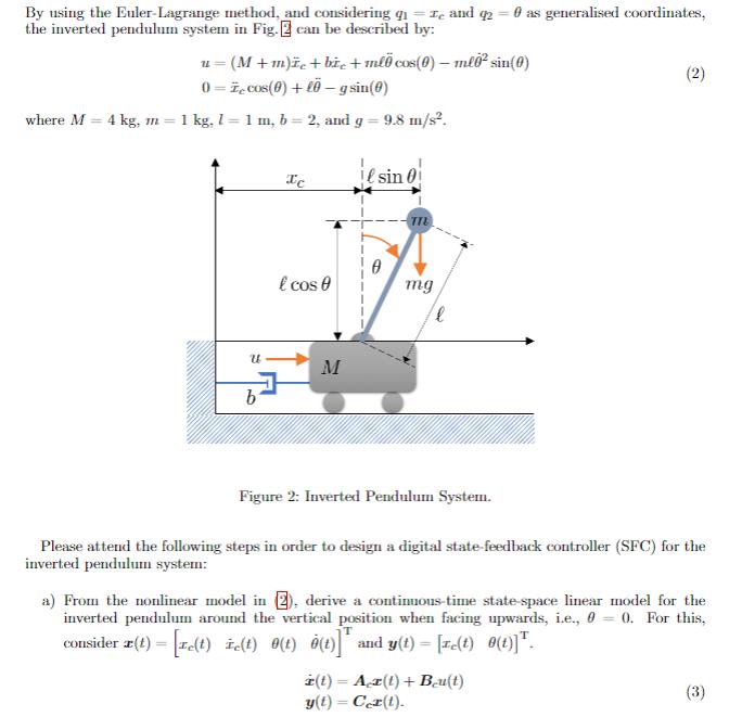
By using the Euler-Lagrange method, and considering g = 1 and q2 = 0 as generalised coordinates, the inverted pendulum system in Fig. 2 can be described by: u= (M+m)e+be+ml cos(0) ml0 sin(0) 0= cos(0)+l-g sin(0) - (2) where M = 4 kg, m = 1 kg, 11 m, b = 2, and g = 9.8 m/s. Te sin 0 U b l cos mg l M Figure 2: Inverted Pendulum System. Please attend the following steps in order to design a digital state-feedback controller (SFC) for the inverted pendulum system: a) From the nonlinear model in 2), derive a continuous-time state-space linear model for the inverted pendulum around the vertical position when facing upwards, i.e., 00. For this, consider x(t)= [re(t) = [re(t) te(t) (t) 0(t)] and y(t) = [re(t) 0(t)]. (t) = Ax(t)+ Bu(t) y(t) = Cex(t). (3)
Step by Step Solution
There are 3 Steps involved in it
Step: 1
Part a Derive ContinuousTime StateSpace Model Given the nonlinear model u M mddotxc bdotxc m ell ddo...
Get Instant Access with AI-Powered Solutions
See step-by-step solutions with expert insights and AI powered tools for academic success
Step: 2

Step: 3
Ace Your Homework with AI
Get the answers you need in no time with our AI-driven, step-by-step assistance
Get Started