Question: can i get a solution to this question please. Value: Document (include your file name) 15% of final grade How to complete: 1. Read the
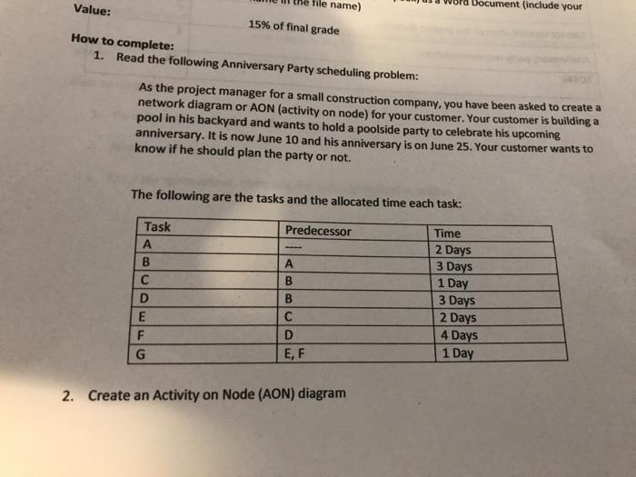
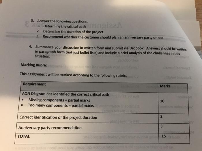
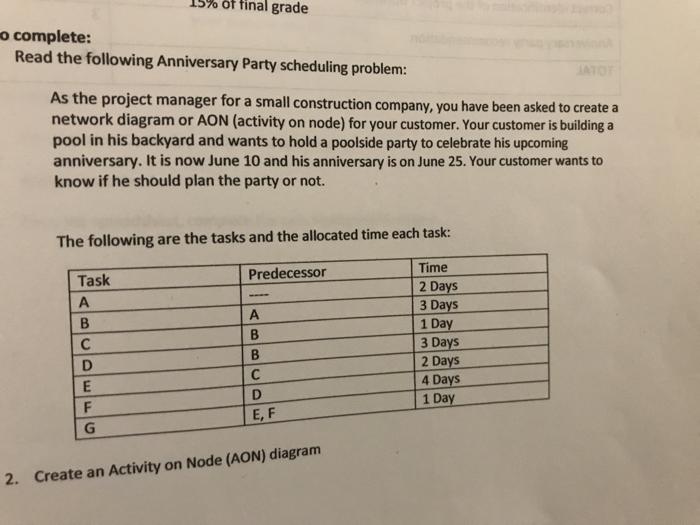
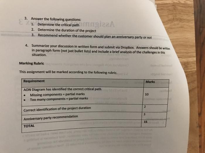
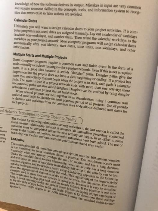
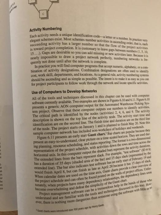
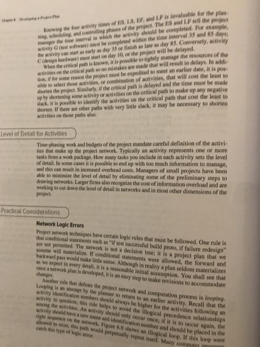
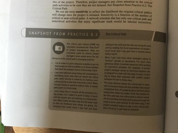

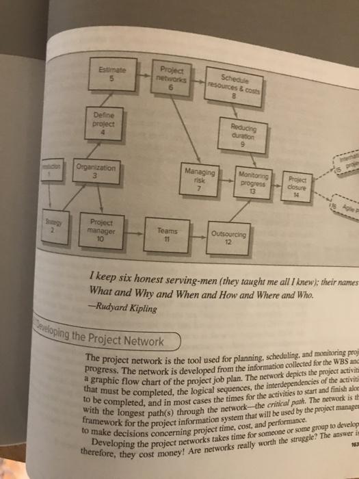
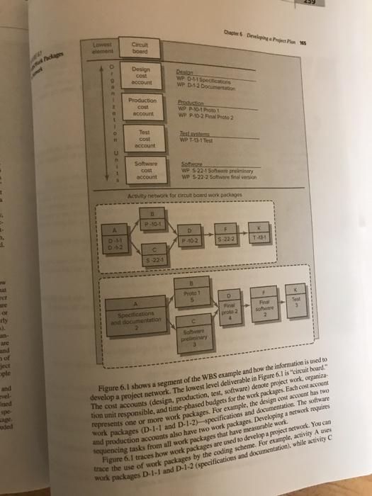
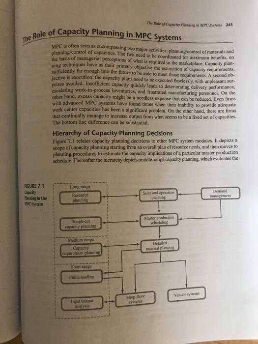
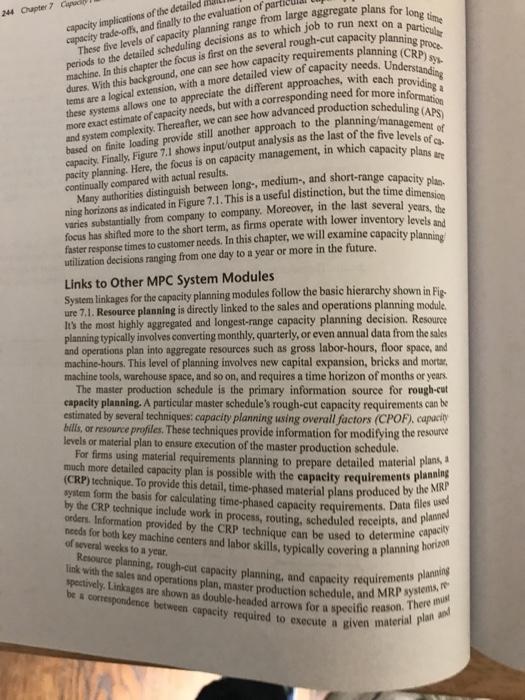
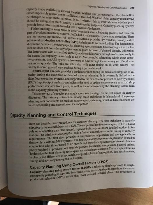
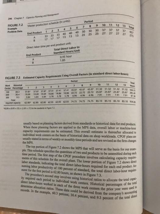
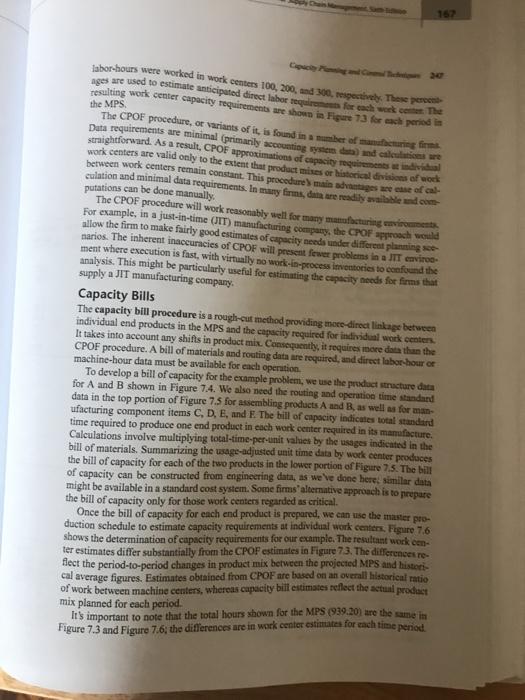
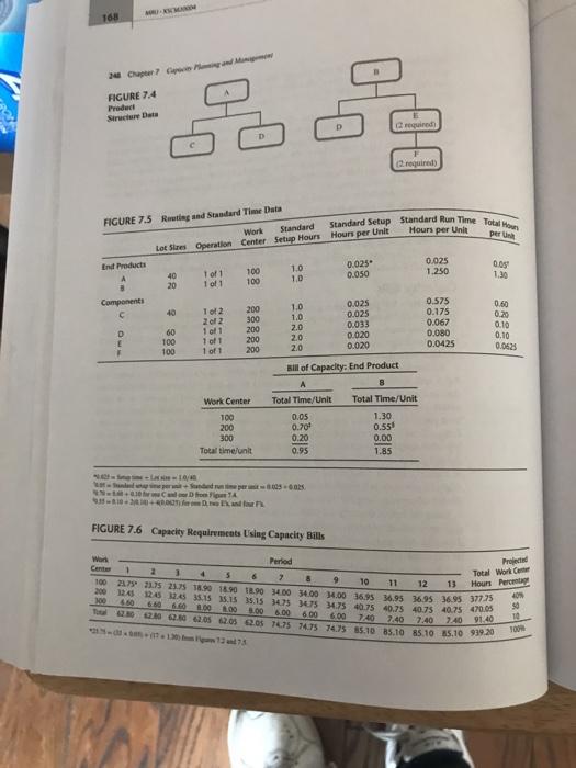
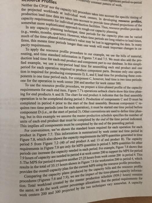
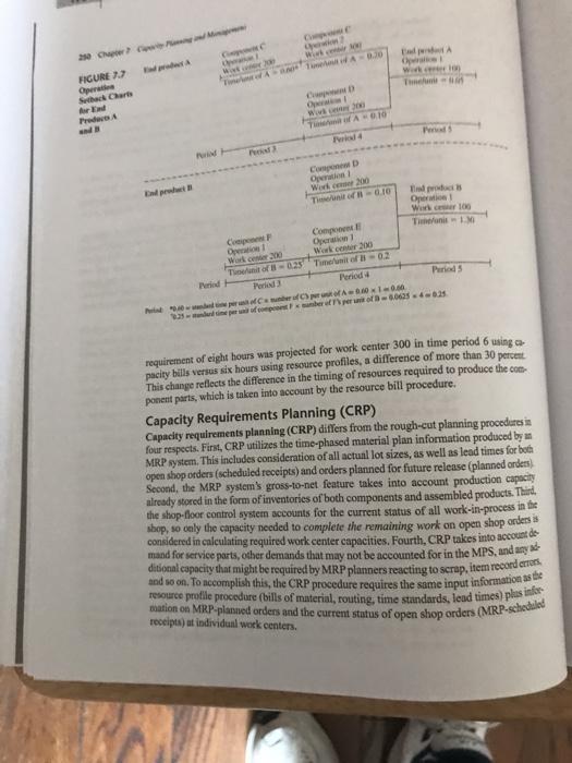
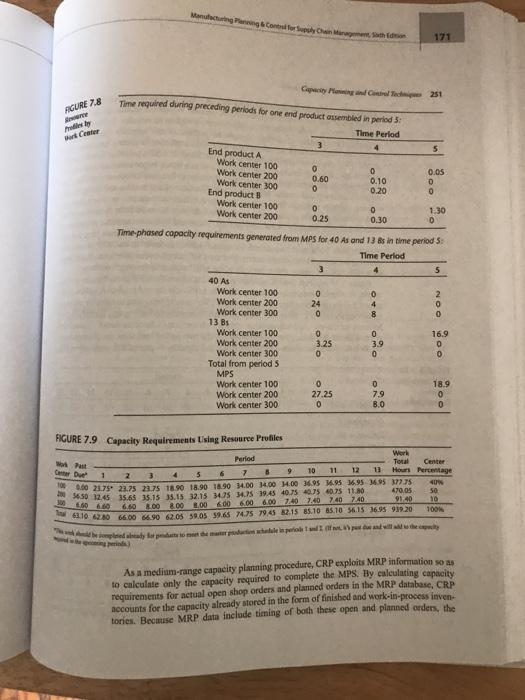
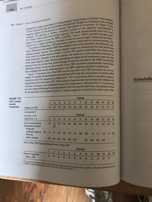
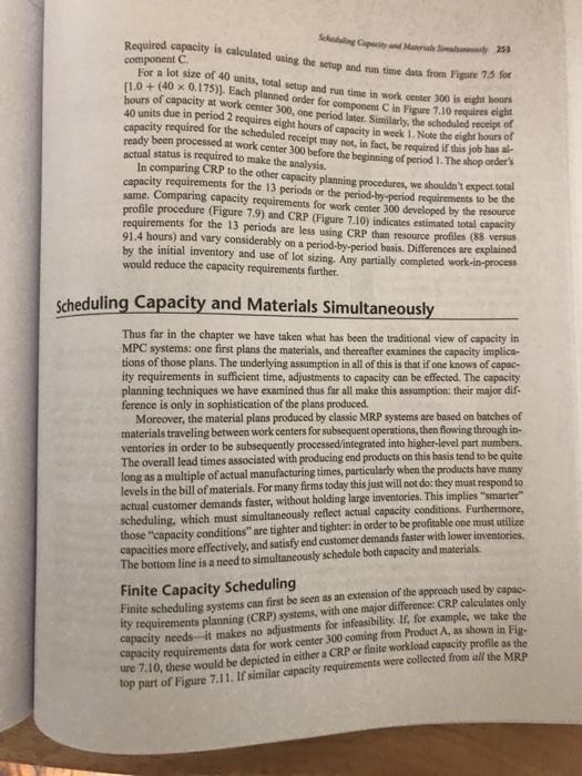
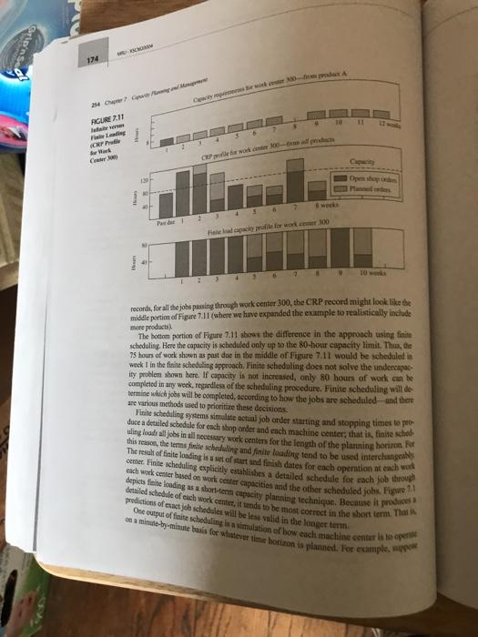
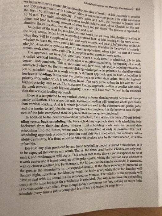
Value: Document (include your file name) 15% of final grade How to complete: 1. Read the following Anniversary Party scheduling problem: As the project manager for a small construction company, you have been asked to create a network diagram or AON (activity on node) for your customer. Your customer is building a pool in his backyard and wants to hold a poolside party to celebrate his upcoming anniversary. It is now June 10 and his anniversary is on June 25. Your customer wants to know if he should plan the party or not. The following are the tasks and the allocated time each task: Predecessor Task B D A B B C D E, F Time 2 Days 3 Days 1 Day 3 Days 2 Days 4 Days 1 Day E F G 2. Create an Activity on Node (AO) diagram 3. Answer the following questions: 1. Determine the critical path 22A 2. Determine the duration of the project 3. Recommend whether the customer should plan an anniversary party or not 4. Summarize your discussion in written form and submit via Dropbox. Answers should be written in paragraph form (not just bullet lists) and include a brief analysis of the challenges in this situation. Marking Rubric o bobo This assignment will be marked according to the following rubric. Requirement Marks AON Diagram has identified the correct critical path Missing components = partial marks Too many components = partial marks 10 . Correct identification of the project duration N 3 Anniversary party recommendation TOTAL 15 of tinal grade complete: Read the following Anniversary Party scheduling problem: As the project manager for a small construction company, you have been asked to create a network diagram or AON (activity on node) for your customer. Your customer is building a pool in his backyard and wants to hold a poolside party to celebrate his upcoming anniversary. It is now June 10 and his anniversary is on June 25. Your customer wants to know if he should plan the party or not. The following are the tasks and the allocated time each task: Predecessor Task B D E F G B B Time 2 Days 3 Days 1 Day 3 Days 2 Days 4 Days 1 Day E, F 2. Create an Activity on Node (AON) diagram 3. Answer the following questions: 1. Determine the critical pathirgizzA 2. Determine the duration of the project 3. Recommend whether the customer should plan an anniversary party or not 4. Summarize your discussion in written form and submit via Dropbox. Answers should be written in paragraph form (not just bullet lists) and include a brief analysis of the challenges in this situation Marking Rubric This assignment will be marked according to the following rubric. Requirement Marks AON Diagram has identified the correct critical path Missing components = partial marks Too many components - partial marks 10 2 Correct identification of the project duration 3 Anniversary party recommendation 15 TOTAL Summary Chapter 6 Developing a Project Plan 19 Many project managers feel the project network is their most valuable exercise and planning document. Project networks sequence and time-phase the project work. resources, and budgets. Work package tasks are used to develop activities for networks. Every project manager should feel comfortable working in an AON envi- ronment. The AON method uses nodes (boxes) for activities and arrows for dependencies. The forward and backward passes establish early and late times for activities. Although most project managers use computers to generate networks and activity times, they find a keen understanding of network development and the abil- ity to compute activity times is invaluable in the field. Computers break down input errors give false information; some decisions must be made without computer what if" analysis. Project managers who are well acquainted with network development and AON methods and who are able to compute activity times will encounter fewer problems than project managers less well acquainted. Project networks help to ensure there are no surprises. Several extensions and modifications have been appended to the original AON method. Lags allow the project planner to more closely replicate the actual conditions found in practice. The use of lags can result in the start or finish of an activity becom. ing critical. Some computer software simply calls the whole activity critical rather than identifying the start or finish as being critical. Caution should be taken to ensure that lags are not used as a buffer for possible errors in estimating time. Finally, hammock activities are useful in tracking costs of resources used for a particular segment of a project. Hammock activities can also be used to reduce the size of a project network by grouping activities for simplification and clarity. All of the discussed refinements to the original AON methodology contribute toward better planning and control of projects, Latetime, 100 Mergestivity, 100 FIGURE 6.17 Finish-to-Finish Relationship Prototype Test expedited (Turtle, 1994). Start-to-start relationships can depict the concurrent engineer ing conditions and reduce network detail. Of course, the same result can be accom- plished by breaking an activity into small packages that can be implemented in parallel, but this latter approach increases the network and tracking detail significantly Finish-to-Finish Relationship This relationship is found in Figure 6.17. The finish of one activity depends on the fin ish of another activity. For example, testing cannot be completed any earlier than bisa days after the prototype is complete. Note that this is not a finish-to-start relationship because the testing of subcomponents can begin before the prototype is completed, but four days of "system" testing is required after the prototype is finished. Start-to-Finish Relationship This relationship represents situations in which the finish of an activity depends on the start of another activity. For example, system documentation cannot end until three days after testing hus started (see Figure 6.18). Here all the relevant information to complete the system documentation is produced after the first three days of testing. Combinations of Lag Relationships More than one lag relationship can be attached to an activity. These relationships are usually start-to-start and finish-to-finish combinations tied to two activities. For exam. ple, debug cannot begin until two time units after coding has started. Coding must be finished four days before debug can be finished (see Figure 6.19). An Example Using Lag Relationships--The Forward and Backward Pass The forward and hackward pass procedures are the same as explained earlier in the clupter for finish-to-start relationships (without lags). The modifying technique lies in the need to check each new relationship to see if it alter the start or finish time of another activity FIGURE 6.20 New A De 0 5 FIGURE 6.18 Start-to-Finish Relationship documento FIGURE 6.19 Lagu Chapter Deweloping Projection 107 An example of the outcome of the forward and backward pass is shown in Fig. ure 6.20. Order hardware depends upon the design of the system (start-to-start). Three days into the design of the system (activity A), it is possible to order the required hard- ware (activity B). It takes four days after the order is placed (activity B) for the hard- ware to arrive so it can begin to be installed activity C). After two days of installing the software system (activity D), the testing of the system can begin (activity E). System testing (activity E) can be completed two days after the software is installed (activity D). Preparing system documentation (activity 5) can begin once the design is com pleted (activity A), but it cannot be completed until two days after testing the system Note how an activity can have a critical finish and/or start. Activities E and F have critical finishes (zero slack), but their activity starts have 4 and 12 days of slack. It is only the finishes of activities E and F that are critical. Conversely, activity A has zero slack to start but has five days of slack to finish. The critical path follows activity start and finish constraints that occur due to the use of the additional relationships available and the imposed lags. You can identify the critical path in Figure 6.20 by following the dashed line on the network. If a lag relationship exists, each activity must be checked to see if the start or finish is constrained. For example, in the forward pass the EF of activity E (test system) (18) is controlled by the finish of activity D (install software) and the lag of two time units (16+ lng 2 = 18). Finally, in the backward pass, the LS of activity A (design system) is controlled by activity B (order hardware) and the lag relationship to activity A (3 - 3=0). A Network Using Laps 5 F 20 0 12 System documentation 5 3 20 17 18 12 E Lag 2 Lag 2 o 4 Test system 19 16 10 10 L2 10 O DO O sofie . 0 8 hardware 10 2 10 Lay pipe 13 Ly V3 Lay pipe Re va Reti V3 13 the tes her Use of Lags to Reduce Schedule Detail and Project Duration The use of lags has been developed to offer greater flexibility in network construction. A lag is the minimum amount of time a dependent activity must be delayed to begin or end. The use of lags in project networks occurs for two primary reasons: 1. When activities of long duration delay the start or finish of successor activities, the network designer normally breaks the activity into smaller activities to avoid the long delay of the successor activity. Use of lags can avoid such delays and reduce he TE network detail. 2. Lags can be used to constrain the start and finish of an activity. The most commonly used relationship extensions are start-to-start, finish-to-finish, and combinations of these two. These relationship patterns are discussed in this section. Finish-to-Start Relationship The finish-to-start relationship represents the typical, generic network style used in the early part of the chapter. However, there are situations in which the next activity in a sequence must be delayed even when the preceding activity is complete. For example, removing concrete forms cannot begin until the poured cement has cured for two time units. Figure 6.13 shows this lag relationship for AON networks. Finish-to-start lugs are frequently used when ordering materials. For example, it may take I day to place orders but take 19 days to receive the goods. The use of finish-co-start allows the activity dura- tion to be only 1 day and the lag 19 days. This approach ensures the activity cost is tied to placing the order only rather than charging the activity for 20 days of work. This same finish-to-start lag relationship is useful to depict transportation, legal, and mail lags. The use of finish-to-start lags should be carefully checked to ensure their validity . Con- servative project managers or those responsible for completion of activities have been late. A simple rule to follow is that the use of finish-to-start lags must be justified and is not usually difficult to discern. The legitimate use of the additional relationship shown approved by someone responsible for a large section of the project . The legitimacy of lags can greatly enhance the network by more closely representing the realities of the project. Start-to-Start Relationship An alternative to segmenting the activities as we did earlier is to use a start-to-start relationship. Typical start-to-start relationships are shown in Figure 6.14. Figure 6.14A Lo 19 bowledge of how the software derives its caput. Mistakes in input are very common and require someone skilled in the concepts, tools and information system to recog. nize that errors exist so false actions are avoided. Calendar Dates Uhrimately you will want to assign calendar dates to your project activities. If a com puter program is not used dates are assigned manually. Lay out a calendar of workdays (exclude non-worldays) and number them. Then relate the calendar workdays to the workdays on your project network. Most computer programs will assign calendar dates automatically after you identify start dates, time units, non-workdays, and other information. Multiple Starts and Multiple Projects Some computer programs require a common start and finish event in the form of a node-seally a circle or rectangle--for a project network. Even if this is not a require ment, it is a good idea because it avoids "dangler" paths. Dangler paths give the impression that the project does not have a clear beginning or ending. If a project has more than one activity that can begin when the project is to start, each path is a dangler path. The same is true if a project network ends with more than one activity: these unconnected paths are also called danglers. Danglers can be avoided by tying dangler activities to a common project start or finish node. When several projects are tied together in an organization, using a common start and end node helps to identify the total planning period of all projects. Use of pseudo or dummy wait activities from the common start node allows different start dates for each project ed Network Techniques to Come Closer to Reality The method for showing relationships among activities in the last section is called the finish-to-start relationship because it assumes all immediate preceding connected activities must be completed before the next activity can begin. In an effort to come closer to the realities of projects, some useful extensions have been added. The use of laddering was the first obvious extension practitioners found very useful. Laddering The assumption that all immediate preceding activities must be 100 percent complete is too restrictive for some situations found in practice. This restriction occurs most frequently when one activity overlaps the start of another and has a long duration Under the standard finish-to-start relationship, when an activity has a long duration and will delay the start of an activity immediately following it, the activity can be bro ken into segments and the network drawn using a laddering approach so the following activity can begin wooter and took delay the work. This segmenting of the larger activity example used in many texts and articles is laying pipe, because it is easy to visualize The trench must be hop. pipe laid, and the trench refilled. If the pipeline is one mile long. It is not necessary to dig one mile of trench before the laying of pipe can begin or so lay one mile of pipe before refill can begin. Figure 6.12 saws how these overlap ping civities might appear in an AON network using the standard finish-to-tant approach Activity Numbering Each activity needs a unique identification code alteraber. In elegant schemes exist. Most schemes number activities in ascending order, that is cach succeeding activity has a larger number so that the flow of the project activities is toward project completion. It is customary to leave gaps berwce numbers (1.5.20 15...). Gaps are desirable so you can add missing or new activities later. Becase nearly impossible to draw a project network perfectly, mumbering networks is te quently not done until after the network is complete. In practice you will find computer programs that accept numeric, alphabetic, cra.com bination of activity designations. Combination designations are often used to identity cost, work skill, departments, and locations. As a general rule, ativity numbering systems should be ascending and as simple as possible. The intent is to make it as easy as you can for project participants to follow work through the network and locate specific activities Use of Computers to Develop Networks All of the tools and techniques discussed in this chapter can be used with computer software currently available. Two examples are shown in Figures 6.10 and 6.11. Figure 6.10 presents a generic AON computer output for the Automated Warehouse Picking Sy tem project. Observe that these computer outputs use numbers to identify activities The critical path is identified by the nodes (activities) 2, 4, 6, and 9. The activity description is shown on the top line of the activity node. The activity start time and identification are on the second line. The finish time and duration are on the third line of the node. The project starts on January 1 and is planned to finish May 20. Nove this sample computer network has included non workdays of holidays and weekends. Figure 6. il presents an early start Gantt chart. Bar charts are popular because they present an easy-to-understand, clear picture on a time-scaled horizon. They are used dur ing planning, resource scheduling, and status reporting. The format is a two-dimensional representation of the project schedule, with activities down the rows and time aross the horizontal axis. In this computer output the shaded bus represent the activity duration The extended lines from the bars represent stuck. For example, "test software" ID#8 he ene has a duration of 35 days (shaded area of the bar) and 15 days slack (represented by the extended line). The bar also indicates test software has an early start of February 19 and would finish April 8, but can finish as late as April 29 because it has 15 days of slack When calendar dates are used on the time axis, Gant charts provide a clear overview of the project schedule and can often be found posted on the walls of project offices. Un tunately, when projects have many dependency relationships, the dependency lines on become overwhelming and defeat the simplicity of the Gantt chart Project management software can be a tremendous help in the hands of those who understand and are familiar with the tools and techniques discussed in this text. How ever, there is nothing more dangerous than someone using the software with little or darts were introduced over 100 years ago by Howy Gant Knowing the four activity times of 18, LS, EB, und LF to lovable for the plan- manager the time interval in which the activity should be completed. Fow sample, Activity (text sofware) must be completed within the time intervals and RS duy the activity cm surt as early a day 35 or finish as late as day Conversely, activity C(design hardware) must start on day 10, or the project will be delayed, When the critical path is known, it is possible to tightly manage the resources of the activities on the critical path to no mistakes are made that will result in delays. In addi. tion, if for some reason the project must be expedited to meet an earlier dute, it is pos sible to select those activities, or combination of activities, that will cost the least to shorten the project. Similarly, if the critical path is delayed and the time must be made up by shortening some activity or activities on the critical path to make up any negative slack, it is possible to identify the activities on the critical path that cout the least to shorten. If there are other paths with very little slack, it may be necessary to shorten activities on those paths also Level of Detail for Activities Time-phasing work and budgets of the project mandate careful definition of the activi- ties that make up the project network. Typically an activity represents one or more tasks from a work package. How many tasks you include in each activity sets the level of detail. In some cases it is possible to end up with too much information to manage, and this can result in increased overhead costs. Managers of small projects have been able to minimize the level of detail by eliminating some of the preliminary steps to drawing networks. Larger firms also recognize the cost of information overload and are working to cut down the level of detail in networks and in most other dimensions of the project Practical Considerations Network Logic Errors Project network techniques have certain logie rules that must be followed. One rule is that conditional statements such as "if test successful build proto, if failure redesign are not permitted. The network is not a decision tree; it is a project plan that we assume will materialize. If conditional statements were allowed, the forward and backward pass would make little sense. Although in reality a plan seldom materializes as we expect in every detail, it is a reasonable initial assumption. You shall see that once a network plan is developed, it is an easy step to make revisions to accommodate changes Ashwer rule that defeats the project network and computation process is looping, Looping is an attempt by the planner to return to an earlier activity. Recall that the Nativity Wemitication numbers should always be higher for the activities following an wativy in pansion, this rule helps to wold the illogical precedence relationships mong the activities. An activity should only occar once it is to oceur again, the vysould have a new one wod ideminication number and should be placed in the right wunce on the network. Figure 6.9 shows in illogical loop. If this low were call this type of lope error wirwol to ex, this powth would perpetually repeat itself. Many computer ARGUM ties of the project. Therefore, project managers pay close attention to the critical path activities to be sure they are not delayed. See Snapshot from Practice 6.2: The Critical Path We use the term sensitivity to reflect the likelihood the original critical path(s) will change once the project is initiated. Sensitivity is a function of the number of critical or near-critical paths. A network schedule that has only one critical path and noncritical activities that enjoy significant slack would be labeled insensitive SNAPSHOT FROM PRACTICE 6.2 The Critical Path The critical path method (CPM) has long been considered the "Holy Grail of project management. Here are comments made by veteran project managers when asked about the nificance of the critical path in managing project I try to make it a point whenever possible to put my best people on ticalactites or on those activities that stand the greatest chance of becoming critical I pay the attention when doing the assessment to Identifying those that can impact the critical path the direct or indirectly by maling non critical activity state that it becomes critical When Ive got money to spend to reduce risks, Italy gets spent onclicates I don't have time to monitor the actie dla project, but make a point to rep in touch with the people who are working on tritical acti. De Wien have the time, they are the ones visit to tied out and how things are going. It's amating how much more I can find out from talking to the rank and file who are dolog the work and by reading the facial expressions of people much mom than I can gain from a number-driven status report When I got calls from other managers asking te "bonow people of equipment. I'm much more generous when it involves resources from working on noncritical activities for sample, if another projed mahager needs an electrical engineer who is assigned to atask with five days of slack. I'm ing to share that englove with another project manager for two to three days The most obvious reason the critical path is per tant is because these are the activities that mad completion time. Il suddenly got a call from ab saying they need my project done we were ller than planned, the critical path is where shed ule the over and add extra resources to get project done more quickly. In the same project schedule begins to stop thermal les focus on to get back on the piratnanam Conversely, a sensitive network would be one with more than one critical path and or noncritical activities with very little slack. Under these circumstances the original critical path is much more likely to change once work gets under way on the project. How sensitive is the Automated Warehouse schedule? Not very, since there is only one critical path and the two other noncritical paths have 15 and 35 days of slack, which suggests considerable flexibility. Project managers assess the sensitivity of their network schedules to determine how much attention they should devottoman aging the critical path. 085 Free Slack (Float) Free slack (FS) is unique. It is the amount of time an activity can be delayed without delaying any immediately following successor) activity. Or, free slack is the amount of time an activity can exceed its early finish date without affecting the early start date of any successor(s). Free slack can never be negative. Only activities that occur at the end of a chain of activities, where you have a merge activity, can have free slack. See Figure 6.8, the Automated Warehouse project. In Figure 6.8 activity G has free slack of 15 days, while activities and do not. In this case, activity G is the last activity in the upper puth, and it merges to activity H. Hence, to delay activity G up to 15 days does nor delay any following activities and requires no coordination with managers of other activities. Conversely, if either activ- ity B or D is delayed, the managers of following activities need to be notified that the slack has been used so they can adjust their start schedules. For example, if activity B is delayed 5 days, the manager of activity B should notify those in charge of the fol- lowing activities (D and G) that their slack has been reduced to 10 time units and their carly start will be delayed 5 days. In this example, activity D cannot then start until day 20, which reduces activity D slack to 10 days (LS- ES = SL or 30 - 20 = 10). Free slack for activity G is also reduced to 10 days. Free slack occurs at the last activity in a chain of activities. In some situations the "chain" has only one link. Activity F in Figure 6.8 is an example. It has free slack of 35 days. Note that it needs no coordination with other activities-unless a delay exceeds the free slack of 35 days. (Note: The moment you exceed all free slack avail- able, you delay the project and must coordinate with others who are impacted.) The distinction between free and total slack at first glance seems trivial, but in real- lly it is very important. When you are responsible for a late activity that has zero free slack you impact the schedules of subsequent activities. You should notify the manag ets of the remaining activities in the chain that you will be lato. Again, note that total Mack is shared across the whole puth. Alternatively. If you are responsible for an activ ty that has free slack when you start, you do not need to notify anyone as long as your work does not absorb all of the stack! the forward and Backward Pass Information Returning to the Automated Warehouse project network in Figure 6.8, what does & slack of 35 days for activity F (develop patent request) men for the project manager? In this specifie case it means activity can be delayed 15 days. In a larger sense the project manager soon learns that free slack is important because it allows flexibility in that one parallel activity or another project scheduling scarce project resources personnel and equipe that are used on more Estimate Project networks 6 Schedule resources & Co Define project Reducing duration 9 Organization 3 Monitoring Managing risk 7 progress 3 Project dosure 14 Project manager 10 Teams 11 Outsourcing 12 I keep six honest serving-men (they taught me all I knew); their names What and Why and When and How and Where and Who. --Rudyard Kipling doping the Project Network The project network is the tool used for planning, scheduling, and monitoring proji Progress. The network is developed from the information collected for the WBS an a graphic flow chart of the project job plan. The network depicts the project activit that must be completed, the logical sequences, the interdependencies of the activiti to be completed, and in most cases the times for the activities to start and finish alor with the longest path(s) through the network--the critical pant. The network is te framework for the project information system thar will be used by the project managem to make decisions concerning project time, cost, and performance therefore, they cost money! Are networks really worth the struggle? The answer 1 Dale Don 6 Low Circuit board Design CO account we ooit WP 12 Documentation Production COS Account WP P.101 Photo WP P.10-2 Pelicho2 Test cos! Account Softwa cost account So WP S 2215 premiery WP S-22-2 Stware finansion Activity network for circuit board work packages P10-1 A D DM P-02 S-222 D Pne sowe or ty Specifications od documentation proto 4 are and nor ject ple and Figure 6. I shows a segment of the WBS example and how the information is used to develop a project network. The lowest level deliverable in Figure 6.7 is "circuit board." The cost accounts (design, production, test, software) denore project work, organiza tion unit responsible, and time-phased budgets for the work packages . Each cost accent negresents one or more work packages. For example, the design cost account has two ded work packages (D-1-1 and D-1-2)-specifications and documentation. The software and production accounts also have two work packages. Developing a network requires sequencing tasks from all work packages that have measurable work Figure 6.1 traces how work packages are used to develop a project network. You can trace the use of work packages by the coding scheme. For example, activity Ass work packages D-1-1 and D-1-2 (specifications and documentation, while activity C There limited re- other nec- ervices into ensible, and ork orders. an issue under JIT operations because attention has planning to execution. As a result, actual input should equal actualul put. Actual input becomes actual output with an insignificant delay. The backlog is elicom tively a constant zero. However, planned input can indeed vary from actual input and so can planned output vary from actual output. These variations should be achievable without violating the equality between actual input and actual output with backlog remaining on zero. To the extent that plan-to-actual variations are possible, the result reflects the flexibil- ity, or bandwidth, of the JIT unit. Using the Capacity Plan All the techniques we've described provide data on which a manager can bese a decision. The broad choices are clear--if there's a mismatch between available capacity and required capacity, either the capacity or the material pian should be changed. If capacity is to be changed, the choices include overtime/undertime authorization, hiringlayoff, and increas- ing/ decreasing the number of machine tools or times in use. Capacity requirements can be aterial plan ty planning quirements he detailed tances. The ronment. companies be useful in revisions to as, a change its per day to examine lume would itions could ld be evalu- changed by alternate routing, make-or-buy decisions, subcontracting, raw material substitu- tions, inventory changes, or revised customer promise dates. Choice of capacity planning units can lead to more effective use of the system. Capac ity units need not be work centers as defined for manufacturing, engineering, of routing purposes. They can be groupings of the key resources (human or capital) important in defining the factory's output levels. Many firms plan capacity solely for key machines (work centers) and gateway operations. These key areas can be managed in detail, while other areas fall under resource planning and the shop-floor control system. Capacity planning choices dictate the diameter of the manufacturing pipeline. Only as much material can be produced as there's capacity for its production, regardless of the ma. terial plan. Not understanding the critical nature of managing capacity can lead a firm into production chaos and serious customer service problems. In the same vein, the relationship between flexibility and capacity must be discussed. You can't have perfectly bulunced ma- terial and capacity plans and be able to easily produce emergency orders! We know one preparation. me required, whether ad- ed decision overall fac- important in product mix ther hand, if in capacity general manager who depicts his capacity as a pie. He has one slice for recurring business, one for spare parts production, one for downtime and maintenance, and a final specific slice for opportunity business. He manages to pay for this excess capacity by winning lucrative contracts that require rapid responses. He does not add that opportunity business to a capacity plan fully committed to the other aspects of his business if it's rally important fall short of or exceed capacity calculatio Choice of capacity measure follows directly from the objective of providing capacity to meet production plans. The appropriate measure of capacity that most directly as sources and be based on what's achievable, with allowances for maintenance and other ing these plans. The measure, therefore, should be appropriate to the critical limi essary activities. It must be possible to convert the bundle of products and services capacity measurement terms. The results must be understood by those responsible, they should be monitored. Choice of a Specific Technique into capacity requirements include three different methods for rough-cut capacity plan In this chapter's discussion, the capacity planning techniques for converting a material plan planning, CRP, which is particularly useful for medium range planning. For the detailed (CPOF, capacity bills, and resource profiles). We also examined capacity requiremena choice of method depends heavily on characteristics of the manufacturing environment duy-to-day capacity planning APS systems can be valuable under some circumstances The three rough-cut methods are most general, being applicable even in companies using just-in-time methods for shop-floor control. Rough-cut approaches can be useful in JIT operations to estimate the impact of changes in requirements called for by revisioes y the master production schedule. For example, under level scheduling conditions, a charge from a production rate of 480 units per day (one unit per minute) to 528 units per les (1.1 units per minute) might be needed. A rough-cut procedure could be used to examine the impact on each work center or manufacturing cell through which this volume would pass (including those of suppliers). Any indicated problems or bottleneck conditions could be addressed before the crisis hits. Similarly, a planned reduction in MPS could be exal ated to determine resources that might be freed to work on other tasks. Rough-cut approaches do vary in accuracy, aggregation level, and ease of preparation There's a general relationship between the amount of data and computational time required and the quality and detail of the capacity requirements estimated. The issue is whether ditional costs of supporting more complex procedures are justified by improved deciane making and subsequent plant operations. The capacity bills procedure has an advantage over capacity planning using overali tors (CPOF) because it explicitly recognizes product mix changes. This can be importante JIT operations, particularly where the level schedule is based on assumptions of producten and where different products have different capacity requirements. On the other hand changes in mix are easily accommodated, and there are minimal differences in cap APS systems to focus on the bottlenecks allows smart users to examine the best "skin the cat." maximum effectiveness. Capacity planning techniques can help with the former, bis di The most critical capacity requirements need to be identified and thereafter whilas environments that are easier to execute environments where capacities are utili predictable and stable fashion. Capacity Planning in the MPC System To illustrate the importance of the interrelationships in designing and using the carte decisions on shorter-term capacity planning decisions. To the extent that production ple ning and resource planning are done well , problems faced in capacity planning can be duced, since appropriate resources have been provided. If, for example, the production ple specifies a very stable rate of output, then changes in the master production schedule (MPS) requiring capacity changes are minimal. If the material planning module functions effectively, the MPS will be converted into detailed component production plans with reb tively few unexpected execution problems. A quite different but equally important linkage that can affect capacity planning system design is the linkage with shop-floor execution systems. A key relationship exists in schod uling effective use of capacity. With sufficient capacity and efficient use of that capan ensured by good shop-floor systems, we'll see few unpleasant surprises requiring capa analysis and change. Effective shop-floor procedures utilize available capacity to procese orders according to MRP system priorities, provide insight into potential capacity proble in the short range (a few hours to days), and respond to changes in material plans. Thus & fective systems reduce the necessary degree of detail and intensity of use of the cap a input/output. Again, we see attention to the material planning side of the MPC system, in this case the shop-floor module, baving an effect on the capacity planning side. Choosing the Measure of Capacity Menand Capacity 36) The choice of capacity measures is an important management issue. Alternatives run from machine-hours or labor-hours to physical or monetary units. The choice depends on the constraining resource and the firm's needs. In any manufacturing company, the "bundle of edge work, after-sales service, and other customer services. In every case, providing there developed. Appropriate measures of capacity must be established and changed as evolution in the bundle of goods and services occurs. Several current trends in manufacturing have a significant bearing on the choice of ca. pacity measures. Each can have a major impact on what's important to measure in capacity One important trend is considerable change in the concept of direct labor. Direct labor has been shrinking as a portion of overall manufacturing employment. Distinctions between di- rect and indirect labor are becoming less important. The ability to change labor capacity by hiring and firing (or even using overtime) has been reduced; notions of lifetime employ. ment" have further constrained this form of capacity adjustment. One objective in JIT systems is continual improvement, so the basis for labor capacity is constantly changing. This mandates control procedures for identifying and changing the planning factors as improvements take place. Another important trend is decreased internal fabrication and increased emphasis on outside purchasing, i.e., outsourcing. This trend can alter the conception of what capacity requirements are important. Procurement analysis, incoming inspection, and engineering liaison may become the critical capacities to be managed, as well as planning and sched- uling the capacities in vendor firms. In fact, one of the major benefits ascribed to major outsourcing companies is their ability to more flexibly respond to changing capacity needs. For many firms engaged in fabrication, machine technology is changing rapidly. Flexi- ble automation has greatly increased the range of parts that can be processed in a machine center. Future product mixes are likely to be much more variable than in the past, with a marked effect on the equipment capacity required. Moreover, as equipment becomes more expensive, it may be necessary to plan and control the capacity of key pieces of equipment at a detailed level. To the extent that cellular technologies are adopted as part of JIT manufacturing, the unit of capacity may need to change. Usually the entire cell is coupled and has only as much capacity as its limiting resource. Often, the cell is labor limited, so the unit of capacity is labor-hours (continually adjusted for learning). Sometimes, however, the capacity measure needs to be solely associated with a single aspect of the cell. Also, when dissimilar items are added to the cell for manufacture, it's necessary to estimate each new item's capacity ro- quirements in terms of individual processing steps. The first task in choosing a capacity measure is to creatively identify resources that are critical and in short supply. Capacity control is too complicated to apply to all resources The next step is to define the unit of measure. If the key resource is people, then labor-hours may be appropriate. In other instances, such measures as tons, gallons, number of molds. Capacity Planning and Management In this chapter we discuss the role of capacity planning and management in MPC systems. W focus primarily on techniques for determining the capacity requirements implied by a pre duction plan, master production schedule, or detailed material plans. One managerial prot- lem is to match the capacity with the plans: either to provide sufficient capacity to execut plans, or to adjust plans to match capacity constraints. A second managerial problem wit regard to capacity is to consciously consider the marketplace implications of faster through put times for making products, at the expense of reduced capacity utilization. For example JIT production results in very fast throughput times for manufacturing products, but typ cally some capacities are underutilized. Similarly, by scheduling the highest-priority job through all work centers--taking explicit account of available capacity-it is possible t complete these jobs in much shorter times than under more conventional MPC approaches But this gain in speed for high priority jobs comes at the expense of lower priority job throughput times and some underutilization of capacity. This chapter is organized around five topics: The role of capacity planning in MPC systems: How does it fit, and how is capacity managed in various manufacturing environments? Capacity planning and control techniques: How can capacity requirements be esti- mated and capacity utilization controlled? Scheduling capacity and materials simultaneously: How can finite scheduling tech- miques be applied, and what are the costs/benefits of these techniques? . sions required to plan/utilize capacity most effectively? Management and capacity planning/utilization: What are the critical managerial deci- Example applications: How are techniques for capacity planning applied, and what are some best ? The Role of Capacity Planning in MPC 243 The Role of Capacity Planning in MPC Systems MPC is often seen as encompassing two major activities, planning control of materials and planning control of capacities. The two need to be coordinated for maximum benefits, on the basis of managerial perceptions of what is required in the marketplace. Capacity plan- ning techniques have as their primary objective the estimation of capacity requirements, suficiently far enough into the future to be able to meet those requirements. A second ob- jective is execution: the capacity plans need to be executed flawlessly, with unpleasant sur prises avoided. Insufficient capacity quickly leads to deteriorating delivery performance, escalating work-in-process inventories, and frustrated manufacturing personnel. On the other hand, excess capacity might be a needless expense that can be reduced. Even firms with advanced MPC systems have found times when their inability to provide adequate work center capacities has been a significant problem. On the other hand, there are firms that continually manage to increase output from what seems to be a fixed set of capacities. The bottom line difference can be substantial. Hierarchy of Capacity Planning Decisions Figure 7.1 relates capacity planning decisions to other MPC system modules. It depicts a scope of capacity planning starting from an overall plan of resource needs, and then moves to planning procedures to estimate the capacity implications of a particular master production schedule. Thereafter the hierarchy depicts middle-range capacity planning, which evaluates the FIGURE 7.1 Capacity hug in the Long range Resource planning Sales and operation planning Demand mapement HH Rough-cut capacity planning Master production scheduling Medium range Capacity requirement planning Detailed material planning Short range Finite loading Vendor systems Input/output Shop floor systems 244 Chapter 7 Chu particular capacity implications of the detailed capacity trade-offs, and finally to the evaluation of partic continually compared with actual results. These five levels of capacity planning range from large aggregate plans for long time periods to the detailed scheduling decisions as to which job to run next on a dures. With this background, one can see how capacity requirements planning (CRP) sy machine. In this chapter the focus is first on the several rough-cut capacity planning proce tems are a logical extension, with a more detailed view of capacity needs. Understanding these systems allows one to appreciate the different approaches, with each providing 2 more exact estimate of capacity needs, but with a corresponding need for more information and system complexity. Thereafter, we can see how advanced production scheduling (APS) based on finite loading provide still another approach to the planning management of capacity. Finally, Figure 7.1 shows input/output analysis as the last of the five levels of pacity planning. Here, the focus is on capacity management, in which capacity plans are Many authorities distinguish between long, medium and short-range capacity plan ning horizons as indicated in Figure 7.1. This is a useful distinction, but the time dimension varies substantially from company to company. Moreover, in the last several years, the focus has shifted more to the short term, as firms operate with lower inventory levels and faster response times to customer needs. In this chapter, we will examine capacity planning utilization decisions ranging from one day to a year or more in the future, Links to Other MPC System Modules System linkages for the capacity planning modules follow the basic hierarchy shown in Fig. ure 7.1. Resource planning is directly linked to the sales and operations planning module. It's the most highly aggregated and longest-range capacity planning decision. Resource planning typically involves converting monthly, quarterly, or even annual data from the sales and operations plan into aggregate resources such as gross labor-hours, floor space, and machine-hours. This level of planning involves new capital expansion, bricks and mortar, machine tools, warehouse space, and so on, and requires a time horizon of months or years. The master production schedule is the primary information source for rough-cut capacity planning. A particular master schedules rough-cut capacity requirements can be estimated by several techniques: capacity planning using overall factors (CPOF), capacity bills , or resource profiles. These techniques provide information for modifying the resource levels or material plan to ensure execution of the master production schedule. For firms using material requirements planning to prepare detailed material plans (CRP) technique. To provide this detail, time-phased material plans produced by the MRP much more detailed capacity plan is possible with the capacity requirements planning systern form the basis for calculating time-phased capacity requirements. Data files al by the CRP technique include work in process, routing, scheduled receipts, and planned orden. Information provided by the CRP technique can be used to determine capacity needs for both key machine centers and labor skills, typically covering a planning horizon Resource planning, rough-cut capacity planning, and capacity requirements planning Tink with the sales and operationsplan, master production schedule, and MRP systems, be correspondence between capacity required to execute a given material plann spectively. Linkages are shown as double-headed arrows for a specifio reason. There of several wecks to a year. Capacity Planning and Control Techniques 245 capacity made available to execute the plan. Without this correspondence, the plan will be either impossible to execute or inefficiently executed. We don't claim capacity must always be changed to meet material plans. In fact, whether this is worthwhile or whether plans should be changed to meet capacity is a managerial judgment. Capacity planning systems provide basic information to make that a reasoned judgment. Finite loading in some ways is better seen as a shop scheduling process, and therefore part of production activity control (PAC), but it is also a capacity planning procedure. There are an increasing number of software systems provided by vendors, usually called advanced production scheduling (APS) techniques to do finite loading. The fundamental difference between the other capacity planning approaches and finite loading is that the for- mer set does not consider any adjustment to plans because of planned capacity utilization. The latter starts with a specified capacity and schedules work through work centers only to the extent that capacity is available to do so. Moreover, by scheduling within exact capac ity constraints, the APS systems allow work to flow through the necessary set of work cen ters more quickly. The jobs are scheduled with exact timing on all work centers not merely in some general way, such as during a particular week. Input/output analysis provides a method for monitoring the actual consumption of ca- pacity during the execution of detailed material planning. It is necessarily linked to the shop floor execution systems, and supported by the database for production activity control (PAC). Input/output analysis can indicate the need to update capacity plans as actual shop performance deviates from plans, as well as the need to modify the planning factors used in the capacity planning systems. This overview of capacity planning's scope sets the stage for the techniques the chapter discusses. The primary interaction among these techniques is hierarchical: long-range planning sets constraints on medium-range capacity planning, which in turn constrains de- tailed scheduling and execution on the shop floor. Capacity Planning and Control Techniques Here we describe four procedures for capacity planning. The first technique is capacity planning asing overall factors (CPOF). The simplest of the four techniques, CPOF is based only on accounting data. The second, capacity bills, requires more detailed product infor- mation. The third, resource profiles, adds a further dimension--specific timing of capacity requirements. The first three procedures are rough-cut approaches and are applicable to firms with or without MRP systems. The fourth, capacity requirements planning is used in conjunction with time-phased MRP records and shop-floor system records to calculate ca- pacity required to produce both open shop orders (scheduled receipts) and planned orders To describe the four planning techniques, we use a simple example. The example allows us to clearly see differences in approach, complexity, level of aggregation, data requirements, timing, and accuracy among the techniques. Capacity Planning Using Overall Factors (CPOF) Capacity planning using overall factors (CPOF), a relatively simple approach to rough- eut capacity planning, is typically donc on a manual basis. Data inputs come from the master production schedule (MPS), rather than from detailed material plans. This procedure is 166 245 Chapter 9 12 13 Total FIGURE 7.2 Example Problem Data Master production schedule Period End Product 1 3 5 6 7 8 33 33 33 40 40 40 30 30 17 17 17 13 13 13 25 25 10 11 30 37 37 37 37 25 27 27 27 27 2273 Direct labor time per end product unit: Total Direct Labor In End Product Standard Hours/Unit 0.95 hour 1.85 13 2 3 FIGURE 7.3 Estimated Capacity Requirements Using Overall Factors in standard direct labor hours) Period Historical Center Percentage 1 4 5 7 8 9 10 100 603 37.87 W 4 1741 1741 15.07 45.07 45.07 51 52 51.32 31.32 $6.3 200 30.4 19.00 19.0 19.09 18.6 18.36 18 22.72 222 2222 35.87 29.87 2.8 25.82 ke 100 9.3 5.78 3.75 7.91 7.91 To quind capacity 63.00 62.80 2.80 62,05 6205 62.0574.35 74.7 74.75 85.10 8.10 85.10 8.10 22 0.25 forsendende 12 7312 usually based on planning factors derived from standards or historical data for end products When these planning factors are applied to the MPS data, overall labor or machine-hour capacity requirements can be estimated. This overall estimate is thereafter allocated to individual work centers on the basis of historical data on shop workloads. CPOF plans are usually stated in terms of weekly or monthly time periods and are revised as the firm changes the MPS The top portion of Figure 7.2 shows the MPS that will serve as the basis for our exam ple. This schedule specifies the quantities of two end products to be assembled during each time period. The first step of the CPOF procedure involves calculating capacity require ments of this schedule for the overall plant. The lower portion of Figure 7.2 shows diret luber standards, indicating the total direct labor-hours required for each end product, as suming labor productivity of 100 percent of standard, the total direct labor-hour require ment for the first period is 62.80 hours, as shown in Figure 7.3. The procedure's second step involves using historical ratios to allocate the total capac direct labor-hours worked in each of the three work centers the prior year were used to ity required each period to individual work centers. Historical percentages of the total determine allocation ratios. These data could be derived from the company accounting records. In the example, 60.3 percent, 30.4 percent, and 9.3 percent of the total direct 167 the MPS labor-hours were worked in work centers 100, 200, and y, espectively. These persoon ages are used to estimate anticipated direct inber requales for a week come ne resulting work center capacity requirements are shown in Figure 13 for each period in The CPOF procedure, or variants of it, is found in a number of facturing from Data requirements are minimal (primarily accounting system data)and calculatoare straightforward. As a result, CPOF approximations of capacity requirements individual work centers are valid only to the extent that product mises or historical devises of work between work centers remain constant. This procedure main advantages are ease of cal culation and minimal data requirements. In many forms, data are readily available und.com putations can be done manually. The CPOF procedure will work reasonably well for many manufacturing with For example, in a just-in-time (JIT) manufacturing company, the CPOF approach would allow the firm to make fairly good estimates of capacity needs under different plannings narios. The inherent inaccuracies of CPOF will present fewet problems in a IT vie ment where execution is fast, with virtually no work-in-process inventories to confound the analysis. This might be particularly useful for estimating the capacity needs for firms that supply a JIT manufacturing company. Capacity Bills The capacity bill procedure is a rough-cut method providing more direct linkage between individual end products in the MPS and the capacity required for individual work center It takes into account any shifts in product mix. Consequently, it requires more data than the CPOF procedure. A bill of materials and routing data are required, and direct labor hour ce machine-hour data must be available for each operation To develop a bill of capacity for the example problem, we use the product structure data for A and B shown in Figure 7.4. We also need the routing and operation time standard data in the top portion of Figure 7.5 for assembling products A and B as well as for man ufacturing component items C, D, E, and F. The bill of capacity indicates total standard time required to produce one end product in each work center required in its manufacture. Calculations involve multiplying total-time-per-unit values by the usages indicated in the bill of materials. Summarizing the usage-adjusted unit time data by work center produces the bill of capacity for each of the two products in the lower portion of Figure 7.5. The bill of capacity can be constructed from engineering data, as we've done here: similar diata might be available in a standard cost system. Some firmsalternative approach is to prepare the bill of capacity only for those work centers regarded as critical Once the bill of capacity for each end product is prepared, we can use the master pro- duction schedule to estimate capacity requirements at individual work centers. Figure 7.6 shows the determination of capacity requirements for our example. The resultant work con- ter estimates differ substantially from the CPOF estimates in Figure 73. The differences re- flect the period-to-period changes in product mix between the projected MPs and historia cal average figures. Estimates obtained from CPOF are based on an overall historical ratio of work between machine centers, whereas capacity bill estimates reflect the actual product mix planned for each period. It's important to note that the total hours shown for the MPS (939.20) are the same in Figure 7.3 and Figure 7.6; the differences are in work center estimates for ench time period 168 Ch? FIGURE 7.4 Product Sir Data required required) Work per FIGURE 7.5 Routing and Standard Time Data Standard Setup Standard Run Time Total Standard Hours per Unit Let Sles Operation Center Setup Hours Hours per Unit End Products 0.025 0.025 10 40 1 of 1 0.050 0.05 1.250 20 10 1 of 1 1.30 Components 1 of 2 200 10 0.025 0.575 0.60 zel2 300 1.0 0.025 0.175 D 60 1 of 1 200 2.0 0.033 0.10 100 1 of 1 200 20 0.020 0.080 0.10 100 1 of 1 0.020 2.0 0.0425 0.0625 Bill of Capacity: End Product A 8 Work Center Total Time/Unit Total Time/Unit 100 0.05 1.30 0.70 0.55 300 0.20 0.00 Total time/unit 0.95 1.85 8%88% 88 0.067 200 perder 03.02 FIGURE 7.6 Capacity Requirements Using Capacity Bills 4 6 Pred Total Work Hours Per Wor Period Cente 1 2 1 5 2 9 10 -11 12 13 100 219 22.5 23.75 1890 18.30 TR90 3400 34.00 34.00 36.95 36.95 36.95 36.95 377.25 200 126 13 35.15 2.15 3.15 S 375 3.75 40.75 40.75 0.75 40.75 470.00 100 606000 100.00 6.00 6.00 6.00 7.40 2.40 tom 240 0.0 42.05 2.03 22.05 TUS 74.75 74.75 85.10 85.10 5.10 5.10 99.00 7.40 7.40 91.40 50 10 100 the projected workloads at individual work centies. In developing resource profiles period ely constant pattern of work Neither the CPOF nor the capacity bill procedure takes into account the specific production lead time data are taken into account to provide time-phased projections of the capacity requirements for individual production facilities. Thus, tesource profiles provides somewhat more sophisticated approach to rough-cut capacity planning In any capacity planning technique, time periods for the capacity plan om de varied (e.g., weeks, months, quarters). However, when time periods are long relative to lead times much of the time-phased information's value may be lost in aggregating the data. In many firms, this means time periods longer than one week will mask
Step by Step Solution
There are 3 Steps involved in it
To solve the Anniversary Party scheduling problem follow these steps Steps List of Tasks and Predece... View full answer

Get step-by-step solutions from verified subject matter experts


