Answered step by step
Verified Expert Solution
Question
1 Approved Answer
Can someone help me find the, State Diagram, State transition table and Excitations Table using JK and D flip-flops? If possible, the K-maps and Design.

Can someone help me find the, State Diagram, State transition table and Excitations Table using JK and D flip-flops? If possible, the K-maps and Design.
I know we use 3 bits and there are 3 inputs but I'm confused as to how to go from there.
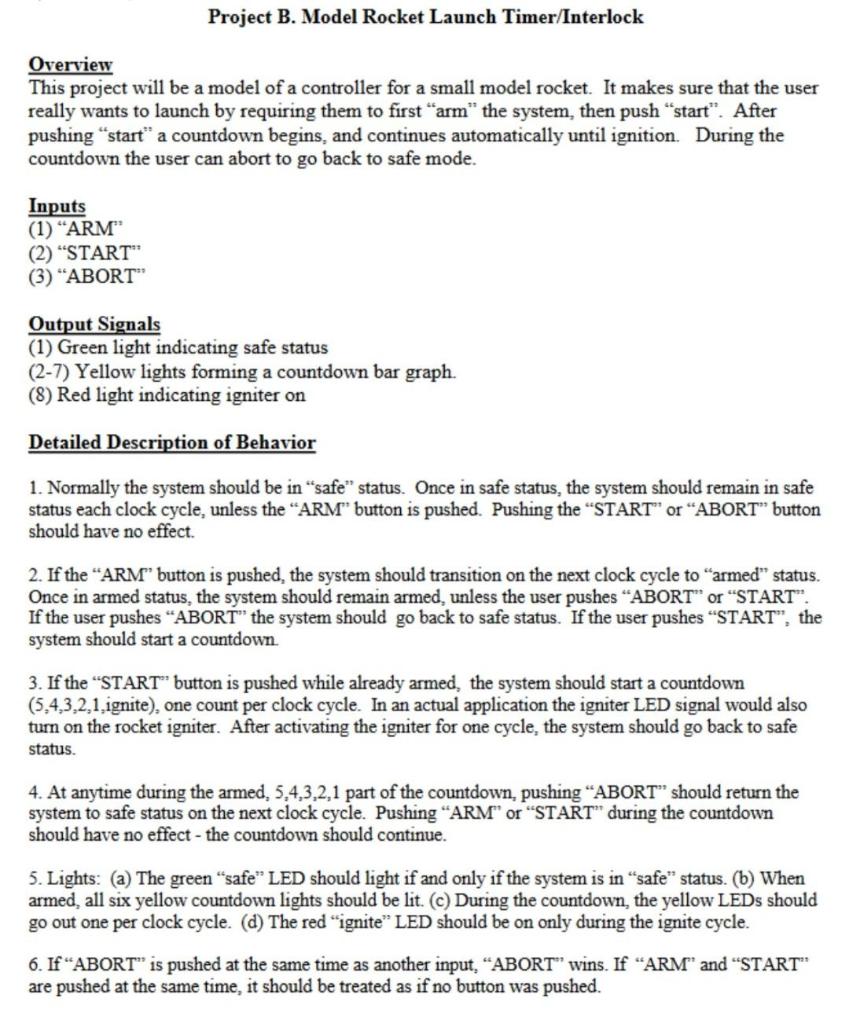
Project B. Model Rocket Launch Timer/Interlock Overview This project will be a model of a controller for a small model rocket. It makes sure that the user really wants to launch by requiring them to first arm" the system, then push "start". After pushing "start" a countdown begins, and continues automatically until ignition. During the countdown the user can abort to go back to safe mode. Inputs (1) ARM (2) "START": (3) "ABORT Output Signals (1) Green light indicating safe status (2-7) Yellow lights forming a countdown bar graph. (8) Red light indicating igniter on Detailed Description of Behavior 1. Normally the system should be in "safe" status. Once in safe status, the system should remain in safe status each clock cycle, unless the "ARM" button is pushed. Pushing the "START" or "ABORT" button should have no effect. 2. If the ARM" button is pushed, the system should transition on the next clock cycle to "armed" status. Once in armed status, the system should remain armed, unless the user pushes ABORT" or "START". If the user pushes ABORT" the system should go back to safe status. If the user pushes "START", the system should start a countdown 3. If the "START" button is pushed while already armed, the system should start a countdown (5,4,3,2,1. ignite), one count per clock cycle. In an actual application the igniter LED signal would also turn on the rocket igniter. After activating the igniter for one cycle, the system should go back to safe status 4. At anytime during the armed, 5,4,3,2,1 part of the countdown, pushing ABORT" should return the system to safe status on the next clock cycle. Pushing ARM" or "START" during the countdown should have no effect - the countdown should continue. 5. Lights: (a) The green "safe" LED should light if and only if the system is in "safe" status. (b) When armed, all six yellow countdown lights should be lit. (C) During the countdown, the yellow LEDs should go out one per clock cycle. (d) The red "ignite" LED should be on only during the ignite cycle. 6. If ABORT" is pushed at the same time as another input, ABORT" wins. If "ARM and "START" are pushed at the same time, it should be treated as if no button was pushed. Project B. Model Rocket Launch Timer/Interlock Overview This project will be a model of a controller for a small model rocket. It makes sure that the user really wants to launch by requiring them to first arm" the system, then push "start". After pushing "start" a countdown begins, and continues automatically until ignition. During the countdown the user can abort to go back to safe mode. Inputs (1) ARM (2) "START": (3) "ABORT Output Signals (1) Green light indicating safe status (2-7) Yellow lights forming a countdown bar graph. (8) Red light indicating igniter on Detailed Description of Behavior 1. Normally the system should be in "safe" status. Once in safe status, the system should remain in safe status each clock cycle, unless the "ARM" button is pushed. Pushing the "START" or "ABORT" button should have no effect. 2. If the ARM" button is pushed, the system should transition on the next clock cycle to "armed" status. Once in armed status, the system should remain armed, unless the user pushes ABORT" or "START". If the user pushes ABORT" the system should go back to safe status. If the user pushes "START", the system should start a countdown 3. If the "START" button is pushed while already armed, the system should start a countdown (5,4,3,2,1. ignite), one count per clock cycle. In an actual application the igniter LED signal would also turn on the rocket igniter. After activating the igniter for one cycle, the system should go back to safe status 4. At anytime during the armed, 5,4,3,2,1 part of the countdown, pushing ABORT" should return the system to safe status on the next clock cycle. Pushing ARM" or "START" during the countdown should have no effect - the countdown should continue. 5. Lights: (a) The green "safe" LED should light if and only if the system is in "safe" status. (b) When armed, all six yellow countdown lights should be lit. (C) During the countdown, the yellow LEDs should go out one per clock cycle. (d) The red "ignite" LED should be on only during the ignite cycle. 6. If ABORT" is pushed at the same time as another input, ABORT" wins. If "ARM and "START" are pushed at the same time, it should be treated as if no button was pushedStep by Step Solution
There are 3 Steps involved in it
Step: 1

Get Instant Access to Expert-Tailored Solutions
See step-by-step solutions with expert insights and AI powered tools for academic success
Step: 2

Step: 3

Ace Your Homework with AI
Get the answers you need in no time with our AI-driven, step-by-step assistance
Get Started


