Can you please mark x and y axis for the plot (graph) of the magnitude impedance ? And image of the graph.

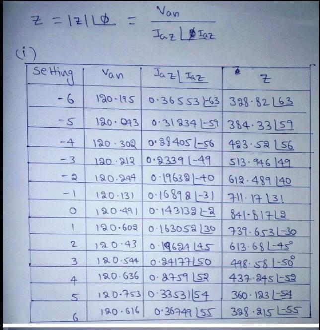
To calculate the impedance z : van/Ia = 120.195/.36553 = 328.82.... Thats all I have. please can you include xy on the graph?

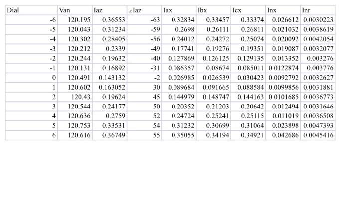
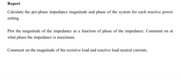
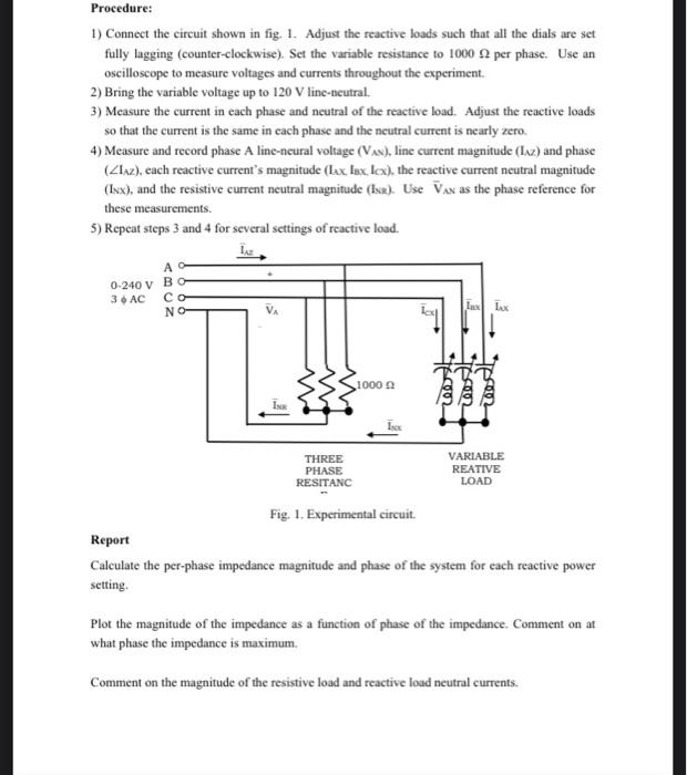
Dial Iaz -6 -5 -4 -3 Van laz 120.195 0.36553 120.043 0.31234 120.302 0.28405 120.212 0.2339 120.244 0.19632 120.131 0.16892 120.491 0.143132 120.602 0.163052 120.43 0.19624 120.544 0.24177 120.636 0.2759 120.753 0.33531 120.616 0.36749 lax Ibx Icx Inx Inr -63 0.32834 0.33457 0.33374 0.026612 0.0030223 -59 0.2698 0.26111 0.26811 0.021032 0.0038619 -56 0.24012 0.24272 0.25074 0.020092 0.0042054 -49 0.17741 0.19276 0.19351 0.019087 0.0032077 -40 0.127869 0.126125 0.129135 0.013352 0.003276 -31 0.086357 0.08674 0.085011 0.0122874 0.003776 -2 0.026985 0.026539 0.030423 0.0092792 0.0032627 30 0.089684 0.091665 0.088584 0.0099856 0.0031881 45 0.144979 0.148747 0.144163 0.0101685 0.0036773 50 0.20352 0.21203 0.20642 0.012494 0.0031646 52 0.24724 0.25241 0.25115 0.011019 0.0036508 54 0.31232 0.30699 0.31064 0.023898 0.0047393 55 0.35055 0.34194 0.34921 0.042686 0.0045416 0 1 2 3 4 5 6 Report Calculate the per-phase impedance magnitude and phase of the system for each reactive power setting Plot the magnitude of the impedance as a function of phase of the impedance. Comment on at what phase the impedance is maximum. Comment on the magnitude of the resistive load and reactive load neutral currents. Nan z =IZILO = Jaz Lolaz () setting van Iaz Iaz e Z 120-1950.36553 -63 328.8263 -5 -4 - 3 - 1 120.043 0.31234 L-59 384 33159 120.302 0.28405L-56 423.52 156. 120 212 0.23394-49 513.946 149 120.244 0.19632-40 612.489 240 120.13) 0:168981-3) 711.17 131 120-491 0.143139-a 841-81712 120.609 0.16305 30 739.6531-30 0.19624 L45 613.684-45 120.544 0.24177150 120.636 o 8759152 437-245-32 120-753 0.3353154 360.12354 0:36749 155 328.215 LESS 1 2 120.43 3 498.581-500 4 5 6 120.616 Procedure: 1) Connect the circuit shown in fig. 1. Adjust the reactive loads such that all the dials are set fully lagging (counter-clockwise). Set the variable resistance to 1000 per phase. Use an oscilloscope to measure voltages and currents throughout the experiment. 2) Bring the variable voltage up to 120 V line-neutral. 3) Measure the current in each phase and neutral of the reactive load. Adjust the reactive loads so that the current is the same in each phase and the neutral current is nearly zero. 4) Measure and record phase A line-neural voltage (Vxx), line current magnitude (Ixz) and phase (Lxz), each reactive current's magnitude (lax. Iux. Lox), the reactive current neutral magnitude (Ixx), and the resistive current neutral magnitude (Isa). Use Vax as the phase reference for these measurements. 5) Repeat steps 3 and 4 for several settings of reactive load. A- 0-240 V BO 3 AC - NO- La lex 1000 cos 2005 THREE PHASE RESITANC VARIABLE REATIVE LOAD Fig. 1. Experimental circuit Report Calculate the per-phase impedance magnitude and phase of the system for each reactive power setting. Plot the magnitude of the impedance as a function of phase of the impedance. Comment on at what phase the impedance is maximum. Comment on the magnitude of the resistive load and reactive load neutral currents. Dial Iaz -6 -5 -4 -3 Van laz 120.195 0.36553 120.043 0.31234 120.302 0.28405 120.212 0.2339 120.244 0.19632 120.131 0.16892 120.491 0.143132 120.602 0.163052 120.43 0.19624 120.544 0.24177 120.636 0.2759 120.753 0.33531 120.616 0.36749 lax Ibx Icx Inx Inr -63 0.32834 0.33457 0.33374 0.026612 0.0030223 -59 0.2698 0.26111 0.26811 0.021032 0.0038619 -56 0.24012 0.24272 0.25074 0.020092 0.0042054 -49 0.17741 0.19276 0.19351 0.019087 0.0032077 -40 0.127869 0.126125 0.129135 0.013352 0.003276 -31 0.086357 0.08674 0.085011 0.0122874 0.003776 -2 0.026985 0.026539 0.030423 0.0092792 0.0032627 30 0.089684 0.091665 0.088584 0.0099856 0.0031881 45 0.144979 0.148747 0.144163 0.0101685 0.0036773 50 0.20352 0.21203 0.20642 0.012494 0.0031646 52 0.24724 0.25241 0.25115 0.011019 0.0036508 54 0.31232 0.30699 0.31064 0.023898 0.0047393 55 0.35055 0.34194 0.34921 0.042686 0.0045416 0 1 2 3 4 5 6 Report Calculate the per-phase impedance magnitude and phase of the system for each reactive power setting Plot the magnitude of the impedance as a function of phase of the impedance. Comment on at what phase the impedance is maximum. Comment on the magnitude of the resistive load and reactive load neutral currents. Nan z =IZILO = Jaz Lolaz () setting van Iaz Iaz e Z 120-1950.36553 -63 328.8263 -5 -4 - 3 - 1 120.043 0.31234 L-59 384 33159 120.302 0.28405L-56 423.52 156. 120 212 0.23394-49 513.946 149 120.244 0.19632-40 612.489 240 120.13) 0:168981-3) 711.17 131 120-491 0.143139-a 841-81712 120.609 0.16305 30 739.6531-30 0.19624 L45 613.684-45 120.544 0.24177150 120.636 o 8759152 437-245-32 120-753 0.3353154 360.12354 0:36749 155 328.215 LESS 1 2 120.43 3 498.581-500 4 5 6 120.616 Procedure: 1) Connect the circuit shown in fig. 1. Adjust the reactive loads such that all the dials are set fully lagging (counter-clockwise). Set the variable resistance to 1000 per phase. Use an oscilloscope to measure voltages and currents throughout the experiment. 2) Bring the variable voltage up to 120 V line-neutral. 3) Measure the current in each phase and neutral of the reactive load. Adjust the reactive loads so that the current is the same in each phase and the neutral current is nearly zero. 4) Measure and record phase A line-neural voltage (Vxx), line current magnitude (Ixz) and phase (Lxz), each reactive current's magnitude (lax. Iux. Lox), the reactive current neutral magnitude (Ixx), and the resistive current neutral magnitude (Isa). Use Vax as the phase reference for these measurements. 5) Repeat steps 3 and 4 for several settings of reactive load. A- 0-240 V BO 3 AC - NO- La lex 1000 cos 2005 THREE PHASE RESITANC VARIABLE REATIVE LOAD Fig. 1. Experimental circuit Report Calculate the per-phase impedance magnitude and phase of the system for each reactive power setting. Plot the magnitude of the impedance as a function of phase of the impedance. Comment on at what phase the impedance is maximum. Comment on the magnitude of the resistive load and reactive load neutral currents


