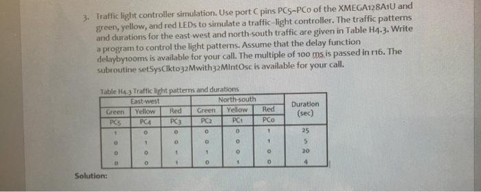
Question: can you please write the code using assembly language. 3. Traffic light controller simulation. Use port pins PC5-PCo of the XMEGA128A10 and green, yellow, and


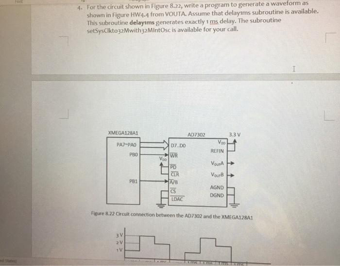
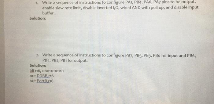
3. Traffic light controller simulation. Use port pins PC5-PCo of the XMEGA128A10 and green, yellow, and red LEDs to simulate a traffic light controller. The traffic patterns and durations for the east west and north-south traffic are given in Table H4.3. Write a program to control the light patterns. Assume that the delay function delaybytooms is available for your call. The multiple of 100 ms is passed in 116. The subroutine setSysCikto32 Mwith32 Mintosc is available for your call. Table Ha3 Traffic light patterns and durations East-west North-south Green Yellow Red Green Yellow Red PCS PCA PC3 PC PC 1 o o 0 Duration (sec) 1 1 O 0 25 5 20 1 0 1 1 0 o o 4 Solution: 4. For the circuit shown in Figure 8.22, write a program to generate a waveform as shown in Figure HW4.4 from VOUTA. Assume that delayims subroutine is available. This subroutine delaytms generates exactly 1 ms delay. The subroutine setSysCikto32Mwith32MIntosc is available for your call. I XMEGA128A1 AD7302 3.3 V PA2-PAO D7..DO VOD REFIN PBO WR Voo PD CLR VOURA VourB PB1 NB CS LDAC AGND DGND Figure 8.22 Circuit connection between the AD7302 and the XMEGA128A1 3V 2V 1V 1. Write a sequence of instructions to configure PA1, PB4, PA6, PA, pins to be output, enable slew rate limit, disable inverted I/O, wired AND with pull-up, and disable input buffer. Solution: 2. Write a sequence of instructions to configure PB7, PB5, PB3, PBo for input and PB6, PB4, PB2, PB1 for output. Solution: Idi 16, ob011010110 out DDRB 116 out Port3,816 3. Traffic light controller simulation. Use port pins PC5-PCo of the XMEGA128A10 and green, yellow, and red LEDs to simulate a traffic light controller. The traffic patterns and durations for the east west and north-south traffic are given in Table H4.3. Write a program to control the light patterns. Assume that the delay function delaybytooms is available for your call. The multiple of 100 ms is passed in 116. The subroutine setSysCikto32 Mwith32 Mintosc is available for your call. Table Ha3 Traffic light patterns and durations East-west North-south Green Yellow Red Green Yellow Red PCS PCA PC3 PC PC 1 o o 0 Duration (sec) 1 1 O 0 25 5 20 1 0 1 1 0 o o 4 Solution: 4. For the circuit shown in Figure 8.22, write a program to generate a waveform as shown in Figure HW4.4 from VOUTA. Assume that delayims subroutine is available. This subroutine delaytms generates exactly 1 ms delay. The subroutine setSysCikto32Mwith32MIntosc is available for your call. I XMEGA128A1 AD7302 3.3 V PA2-PAO D7..DO VOD REFIN PBO WR Voo PD CLR VOURA VourB PB1 NB CS LDAC AGND DGND Figure 8.22 Circuit connection between the AD7302 and the XMEGA128A1 3V 2V 1V 1. Write a sequence of instructions to configure PA1, PB4, PA6, PA, pins to be output, enable slew rate limit, disable inverted I/O, wired AND with pull-up, and disable input buffer. Solution: 2. Write a sequence of instructions to configure PB7, PB5, PB3, PBo for input and PB6, PB4, PB2, PB1 for output. Solution: Idi 16, ob011010110 out DDRB 116 out Port3,816
Step by Step Solution
There are 3 Steps involved in it

Get step-by-step solutions from verified subject matter experts


