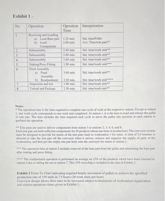
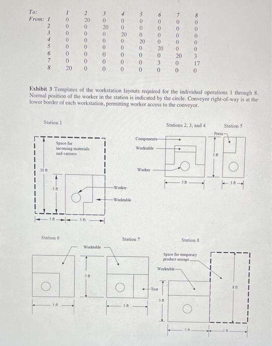
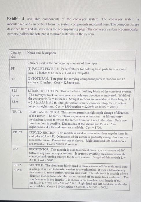
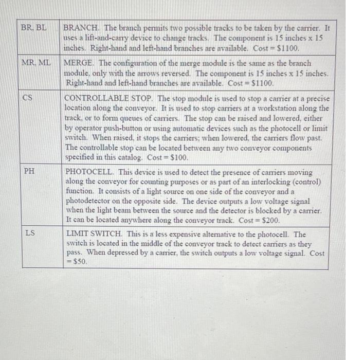
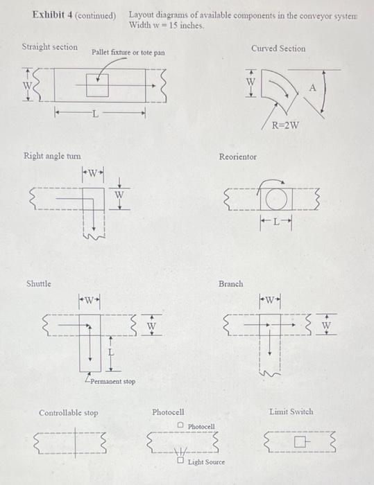
Case Study: Design of a Conveyorized Production Line This case problem is concerned with the design of an assembly line, in particular the aspects of the line that deal with the work organization, layout, and material handling system. The line will be used to produce an electronics-based product used in the automotive industry. The product is a subassembly that weighs approximately 7 lb and consists of a 4 lb dic-cast base part plus electronics and mechanical components added to it. Required production rate is 150 units per day. The plant operates 8.5 hours per day, but with work breaks and occasional line stoppages, the actual productive time is 7.5 hours. Operations Performed on the Line There are eight operations on the line, listed in Exhibit I together with their respective operation times. Material flow is from station to station using an asynchronous conveyor system, as depicted in the From-To Chart of Exhibit 2. The individual workstation layouts for the assembly stations are illustrated in Exhibit 3 with dimensions to be used in the line. All of the stations are operated by human workers. Station 1 is used to collect incoming parts for the line and organize them for movement to the various workstations. The work at station 1 can be divided into two functions. The first function is to load base parts onto pallets for delivery in sequence to the workstations on the line. Each pallet includes a fixture for holding the base part. Except for workstation 5, the assembly work at each station is performed without removing the base part from the pallet fixture. The second function consists of loading the components added at the various stations into tote pans for delivery to stations 2,3,4,6, and 8. Two human workers, one in charge of each function, work in station 1. Stations 2 through 4 are subassembly stations where certain components are assembled and fastened to the base part. Station 5 involves staking and press-fitting using a hand-operated press. This is the only operation in which the subassembly is removed from the pallet and placed in a special workholder. Station 6 is a final assembly operation to ready the product for inspection and testing at Station 7. Station 8 is unloading and packaging, in which finished products are unloaded from their pallets and packaged into cartons for shipping. If the product fails inspection and testing at station 7. it is sent back to Station 6 for readjustment. About 15% of the products fail inspection and test and require readjustment at station 6. After readjustment, units are sent directly from station 6 to station 8. without retesting at station 7. For the operations performed at stations 2,3,4,6,7 and 8, the product remains attached to the respective pallet which stays on the conveyor. Stops are used at each of these stations to keep the pallets in position while work is being performed. After Station 8. pallets are returned to station 1 for reuse. Tote pans, after being emptied at the respective stations, are also returned by placing them back onto the conveyor so they can flow through the system and then return to station 1 Conveyor System A power-and-free conveyor system is used as the material handling system in the line. This conveyor provides for buffers and queues in the line and for stopping and release of the carriers (pallets and tote pans) as regulated by the stations. Different speeds can be programmed in each section of the conveyor, with a maximum speed = 75 ilmin. The width of the conveyor is 15 inches. Both pallets and tote pans are 12 inches wide and are designed specifically for the conveyor system. Diagrams of the possible conveyor components are illustrated in the "catalog" shown in Exhibit 4. The student must decide on the level of conveyor control and automation that is appropriate Assignment The student should submit the following documentation for this conveyorized assembly line design project: 1. Report. The report should detail your analysis of the problem, indicating how the work will be organized, how many workstations for each operation are required, how the conveyor system works to transport materials to the correct stations, and demonstrating that the production requirements of 150 units per day can be satisfied by your design. What are the control issues that must be addressed in the material handling system for this line? The report should summarize the performance measures computed in Section 3 below. 2. Layout Drawing. A layout plan drawing (top view, drawn to scale) of the line. The student must decide how to organize the workstations, how many of each type, and how to arrange the line. The drawing should make use of the templates in Exhibits 3 and 4. These must be redrawn and identified by the student on the layout plan. Use of a computer graphics system is encouraged 3. Analysis and Calculations. The following analysis and/or calculations should be included in your report (your instructor may assign only certain of the following parts) (a) Maximum possible production rate for your design, (b) Average total work content time per unit of product (c) Balance delay for the line, based on total number of workers. (d) How many pallets and tote pans are required to maintain a steady flow of work to the stations? Explain your reasoning and show your calculations (e) Compute the cost of your material handling system design, given the costs of the components presented in the exhibit (1) What is the total floorspace taken up by the system? Exhibit 1 No Operation Operation Interpretation Time 1 1.25 min 2.60 min Std. time/Pallet Avr. Time/tote pan 2 3 4 5 6 Receiving and Loading a) Load Base part b) Load Components Subassembly Subassembly Subassembly Staking/Press Fitting Final Assembly a) Final Assembly b) Readjustment Inspection and test Unload and Package 2.40 min 2.80 min. 2.60 min 190 min Std. time work unit Std. time work unit Std. time work unit Std. time work unit 3.40 min. Std. time work unit 7 8 2.20 min 1.80 min 2.50 min Std. time work unit**** Std. time work unit Std. time/work unit Notes: The operation time is the time required to complete one cycle of work at the respective station. Except at station 1. one work cycle corresponds to one work unit completed. At station 1, it is the time to load and release the pallet or tote pan. The time includes the time required each cycle to move the pallet into position at each station to perform the operation ** Tote pans are used to deliver components from station I to stations 2,3,4,6, and 8. Each tote pan can hold sufficient components for 20 products (about one hour of production). The conveyor system must be designed to provide for return of the tote pans back to workstation 1 for reuse. A time of 2.0 minutes is allowed to take the fote pan off the conveyor when it arrives, remove and organize the supply of parts at the workstation, and then put the empty tote pan back onto the conveyor for return to station 1. *** The operation time at station 5 includes removal of the base part from the pallet and refastening the base part after taking and press fitting. **** The readjustment operation is performed on average on 15% of the products which have been returned to station 6 due to failing the test at station 7. This 15% recycling is included in the data in Exhibit 2. Exhibit 2 From-To Chart indicating required hourly movement of pallets to achieve the specified production rate of 150 units in 75 hours (20 work units per hour). Conveyor design allows flow rates to be increased subject to limitations of workstation organization and station operations times given in Exhibit 1. To: From: 1 2 3 4 5 6 7 8 1 0 0 0 0 0 0 0 20 2 20 0 0 0 0 0 0 0 3 0 20 0 0 0 0 0 0 4 0 0 20 0 0 0 0 0 S 0 0 0 20 0 0 0 0 6 0 0 0 0 20 0 3 0 7 0 0 0 0 0 20 0 0 8 0 0 0 0 0 3 17 0 Exhibit 3 Templates of the workstation layouts required for the individual operations 1 through 8. Normal position of the worker in the station is indicated by the circle. Conveyor right-of-way is at the lower border of each workstation, permitting worker access to the conveyor. Station 1 Stations 2, 3, and 4 Station 3 Press Component 1 1 Space for incoming materials and camers Werktable 51 10 n Worker 51 30 50 -Worker -Worktable ste Station 6 Station 7 Station 8 Werktable Space for temporary product storage Worktable S O . Test 5 50 51 Exhibit 4 Available components of the conveyor system. The conveyor system is modularized and can be built from the system components indicated here. The components are described here and illustrated on the accompanying page. The conveyor system accommodates carriers (pallets and tote pans) to move materials in the system Catalog No Name and description PF $2.5 S3.75 S5.0 TR TL Carriers used in the conveyor system are of two types: (1) PALLET FIXTURE. Pallet fixtures for holding base parts have a square base, 12 inches x 12 inches. Cost = $100 pallet. (2) TOTE PAN. Tote pans for carrying component parts to stations are 12 inches x 12 inches. Cost = $25/tote pan. STRAIGHT SECTION. This is the basic building block of the conveyor system. The conveyor track moves carriers in only one direction as indicated Widtis of the conveyor is W - 15 inches. Straight sections are available in three lengths:L = 2.5 ft. 3.75 ft. 5.0 ft. Straight sections can be connected together to obtain longer strnight runs. Cost = 5500 section + $200/ft, or $(500 + 200L). RIGHT ANGLE TURN. This section permits a night angle change of direction of the carrier. The carrier retains its previous orientation. A lift-and-cury mechanism is used to switch the camer from one track to the other. Only one direction flow is possible. Dimensions of the section are 15 in x 15 in Right-hand and left-hand tums are available. Cost = $700. CURVED SECTION. This module is used to make other than angular tuums multiples of A = 45 Orientation of the carrier is gradually changed as it moves around the curve. Dimensions are as shown. Right-hand and left-hand curves are available. Cost = $800/45 section. REORIENTOR. This module is used to reorient carriers in increments of 90 between any two conveyor sections. It operates by lifting the carrier above the conveyor and rotating through the desired amount. Length of this module L- 2.5 ft. Cost-$900. SHUTTLE. The shuttle module is used to move carriers off the main track onto a siding. It is used to transfer carriers to a workstation. It uses a lift-and-carry mechanism to move carriers onto the side track. The side track is capable of two direction motion to transfer the carriers on and off the main track as desired. The shuttle comes in two lengths (L is shown in the template, total length of the module is L+W):1-25 ft and 5.0 ft Right-hand and left-hand access shuttles are available. Cost-$1000 section + S200/ft or S(1000 + 2001) CR. CL RO SH2.5 SH5.0 BR, BL X MR. ML CS BRANCH. The branch permits two possible tracks to be taken by the carrier. It uses a lift-and-cany device to change tracks. The component is 15 inches x 15 inches. Right-hand and left-hand branches are available. Cost = $1100. MERGE. The configuration of the merge module is the same as the branch module. only with the arrows reversed. The component is 15 inches x 15 inches. Right-hand and left-hand branches are available. Cost = $1100. CONTROLLABLE STOP. The stop module is used to stop a carrier at a precise location along the conveyor. It is used to stop carriers at a workstation along the track, or to form queues of carriers. The stop can be raised and lowered, either by operator push-button or using automatic devices such as the photocell or limit switch. When raised, it stops the carriers: when lowered the carriers flow past. The controllable stop can be located between any two conveyor components specified in this catalog. Cost = $100. PHOTOCELL. This device is used to detect the presence of carriers moving along the conveyor for counting purposes or as part of an interlocking (control) function. It consists of a light source on one side of the conveyor and a photodetector on the opposite side. The device outputs a low voltage signal when the light beam between the source and the detector is blocked by a carrier. It can be located anywhere along the conveyor track. Cost = $200. LIMIT SWITCH. This is a less expensive alternative to the photocell. The switch is located in the middle of the conveyor track to detect carriers as they pass. When depressed by a carrier, the switch outputs a low voltage signal. Cost = $50 PH LS Exhibit 4 (continued) Layout diagrams of available components in the conveyor system Width w = 15 inches Straight section Pallet fixture or tote pan Curved Section R=2W Right angle tum Reorientor * Way w TI Shuttle Branch *W* *** W- towa W W | Permanent stop Controllable stop Photocell Limit Switch Photocell 3 Light Source