Answered step by step
Verified Expert Solution
Question
1 Approved Answer
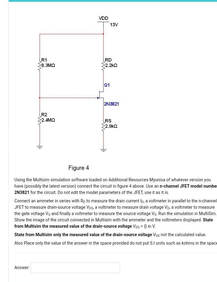
R1 >8.3 R2 2.4 Answer: VDD 13V RD >2.2 Q1 2N3821 RS >2.9k Figure 4 Using the Multisim simulation software loaded on Additional Resources

R1 >8.3 R2 2.4 Answer: VDD 13V RD >2.2 Q1 2N3821 RS >2.9k Figure 4 Using the Multisim simulation software loaded on Additional Resources Myunisa of whatever version you have (possibly the latest version) connect the circuit in figure 4 above. Use an n-channel JFET model number 2N3821 for the circuit. Do not edit the model parameters of the JFET, use it as it is. Connect an ammeter in series with Rp to measure the drain current lo, a voltmeter in parallel to the n-channel JFET to measure drain-source voltage Vos, a voltmeter to measure drain voltage Vp, a voltmeter to measure the gate voltage VG and finally a voltmeter to measure the source voltage Vs. Run the simulation in MultiSim. Show the image of the circuit connected in Multisim with the ammeter and the voltmeters displayed. State from Multisim the measured value of the drain-source voltage VDs = {} in V. State from Multisim only the measured value of the drain-source voltage Vps not the calculated value. Also Place only the value of the answer in the space provided do not put S.I units such as kohms in the space
Step by Step Solution
★★★★★
3.48 Rating (164 Votes )
There are 3 Steps involved in it
Step: 1
Multisim circuit as described in part 41 can be connected as shown be...
Get Instant Access to Expert-Tailored Solutions
See step-by-step solutions with expert insights and AI powered tools for academic success
Step: 2

Step: 3

Ace Your Homework with AI
Get the answers you need in no time with our AI-driven, step-by-step assistance
Get Started


