Question: CHARGE TO MASS RATIO FOR THE ELECTRON OBJECTIVE: To measure the ratio of the charge of an electron to its mass. METHOD: A stream of
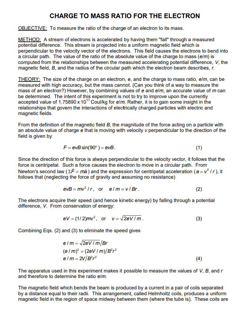
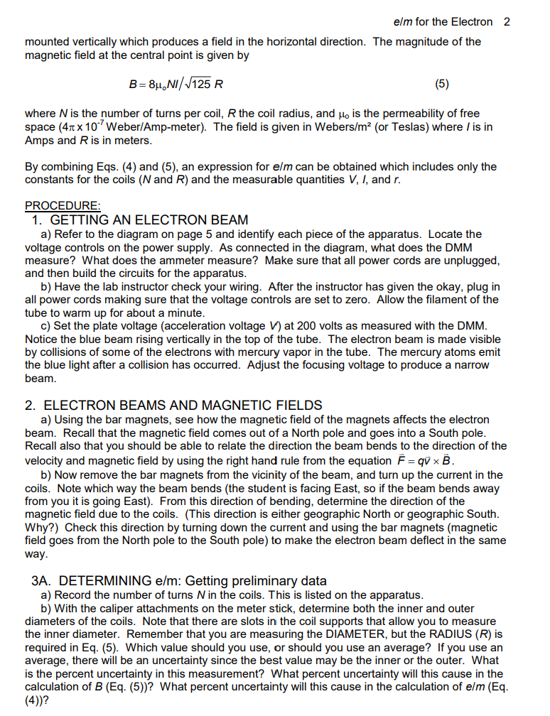
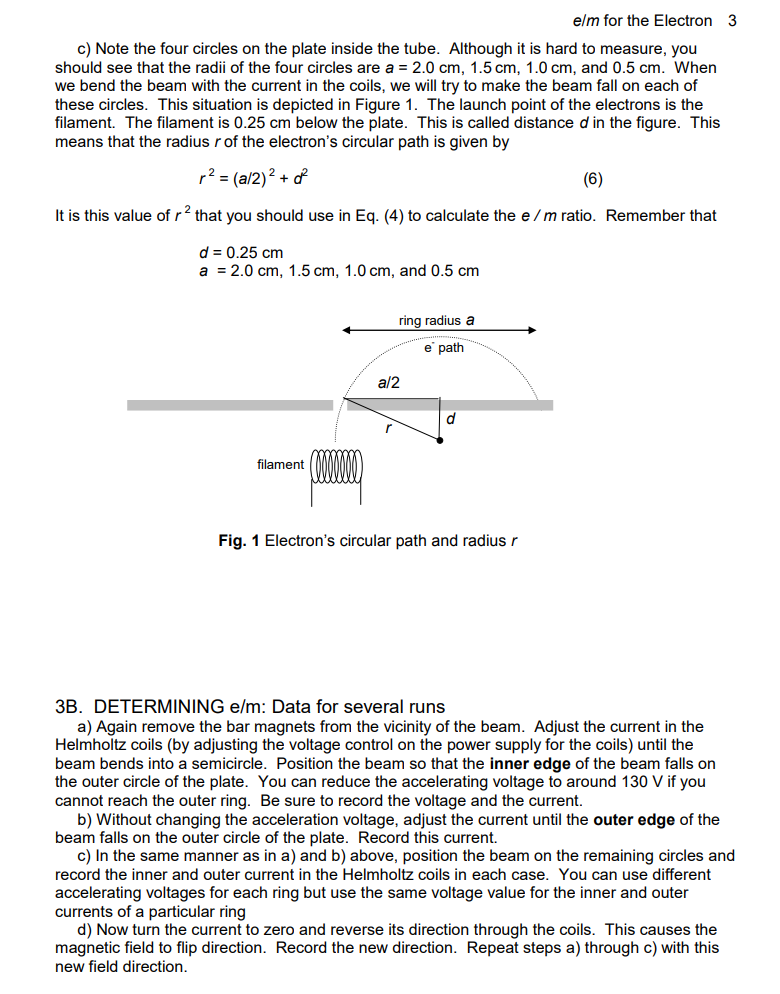
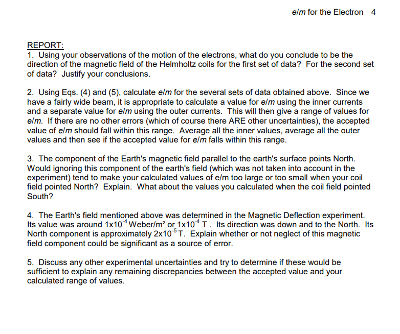
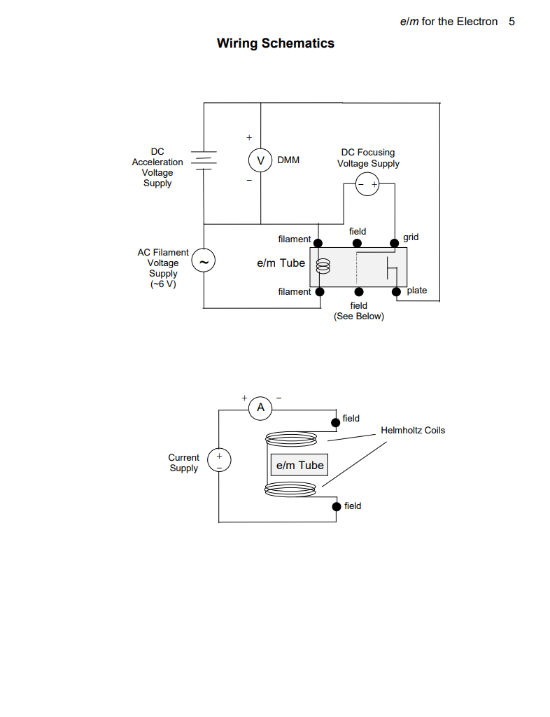
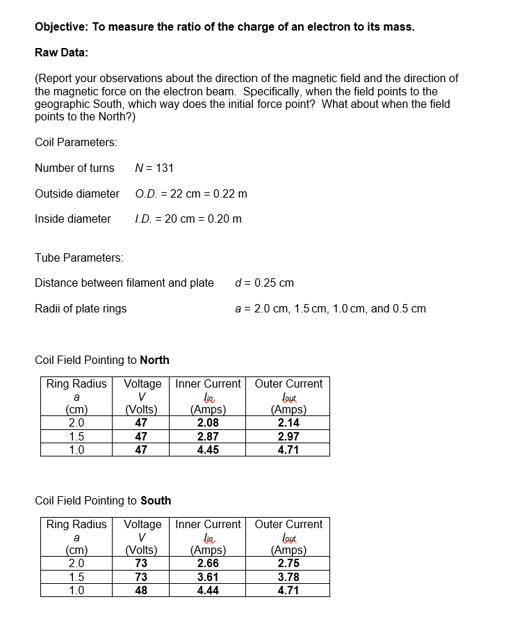
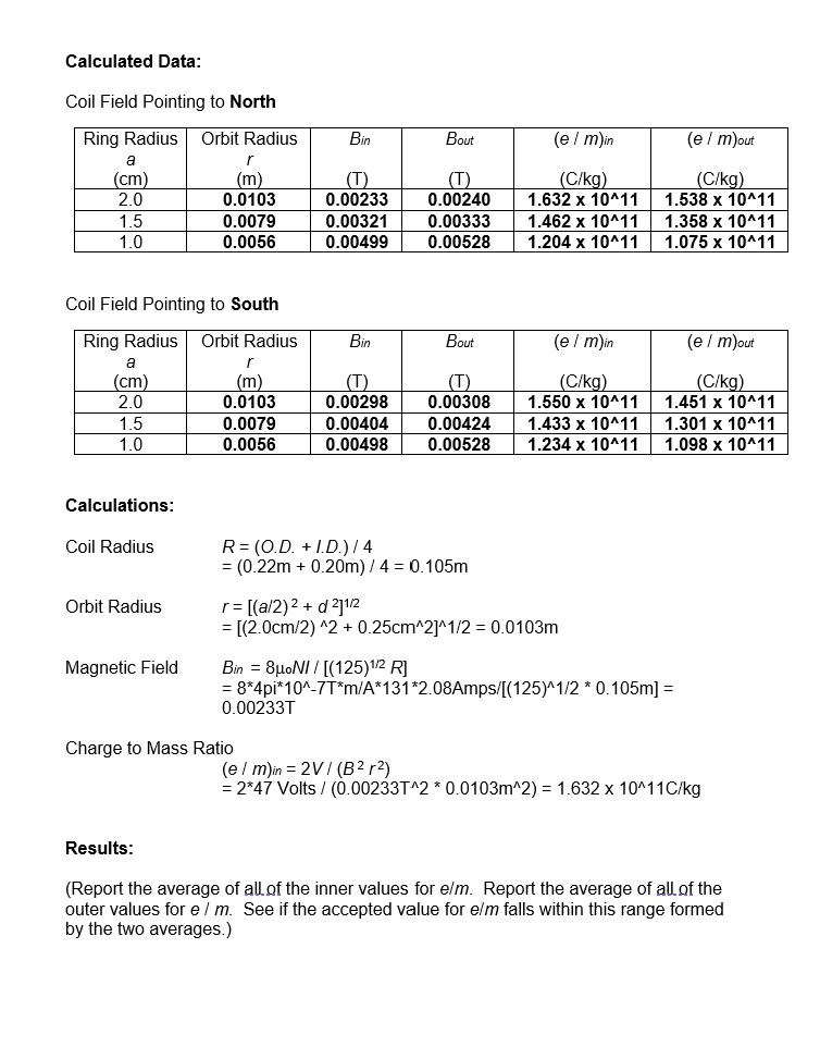
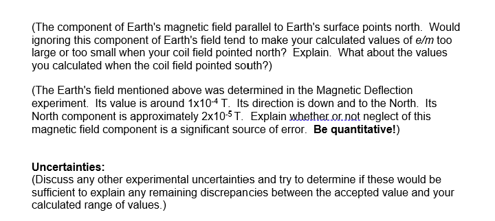
CHARGE TO MASS RATIO FOR THE ELECTRON OBJECTIVE: To measure the ratio of the charge of an electron to its mass. METHOD: A stream of electrons is accelerated by having them "fall" through a measured potential difference. This stream is projected into a uniform magnetic field which is perpendicular to the velocity vector of the electrons. This field causes the electrons to bend into a circular path. The value of the ratio of the absolute value of the charge to mass (e/m) is computed from the relationships between the measured accelerating potential difference, V, the magnetic field, B, and the radius of the circular path which the electron beam describes, r. THEORY: The size of the charge on an electron, e, and the charge to mass ratio, elm, can be measured with high accuracy, but the mass cannot. (Can you think of a way to measure the mass of an electron?) However, by combining values of e and e/m, an accurate value of m can be determined. The intent of this experiment is not to try to improve upon the currently accepted value of 1.75890 x 10"Coul/kg for e/m. Rather, it is to gain some insight in the relationships that govern the interactions of electrically charged particles with electric and magnetic fields. From the definition of the magnetic field B, the magnitude of the force acting on a particle with an absolute value of charge e that is moving with velocity v perpendicular to the direction of the field is given by F = evB sin(90 ) = evB. (1) Since the direction of this force is always perpendicular to the velocity vector, it follows that the force is centripetal. Such a force causes the electron to move in a circular path. From Newton's second law ( EF = ma ) and the expression for centripetal acceleration (a = v / r), it follows that (neglecting the force of gravity and assuming no resistance) evB = mv2 /r, or elm=v/Br. (2) The electrons acquire their speed (and hence kinetic energy) by falling through a potential difference, V. From conservation of energy: ev = (1/2)mv2, or v=2eV/m. (3) Combining Eqs. (2) and (3) to eliminate the speed gives e /m = 2eV / m/Br (e/m) = (2eV/ m)/B2p2 elm = 2V/B2r2 (4) The apparatus used in this experiment makes it possible to measure the values of V, B, and r and therefore to determine the ratio elm. The magnetic field which bends the beam is produced by a current in a pair of coils separated by a distance equal to their radii. This arrangement, called Helmholtz coils, produces a uniform magnetic field in the region of space midway between them (where the tube is). These coils areem for the Electron 2 mounted vertically which produces a eld in the horizontal direction. The magnitude of the magnetic eld at the central point is given by B=apDNi/J% R (5} where N is the number of turns per coil, Rthe coil radius' and pc is the permeability of free space (411 x10'7 WeberfAmp-meter). The field is given in Webersim2 (or Teslasl where i' is in Amps and R is in meters. By combining Eqs. (4) and (5). an expression for elm can be obtained which includes only the constants for the coils (N and R) and the measurable quantities V, l. and r. PROCEDURE; 1. GETTING AN ELECTRON BEAM a) Refer to the diagram on page 5 and identify each piece ofthe apparatus. Locate the voltage controls on the power supply. As connected in the diagram. what does the DMM measure? What does the ammeter measure? Make sure that all power cords are unplugged. and then build the circuits for the apparatus. b) Have the lab instructor check your wiring. After the instructor has given the okay plug in all power cords making sure that the voltage controls are set to zero. Allow the lament of the tube to warm up for about a minute. c) Set the plate voltage (acceleration voltage V) at 200 volts as measured with the DMM. Notice the blue beam rising vertically in the top of the tube. The electron beam is made visible by collisions of some of the electrons with mercury vapor in the tube. The mercury atoms emit the blue light after a collision has occurred. Adjust the tocusing voltage to produce a narrow beam. 2. ELECTRON BEAMS AND MAGNETIC FIELDS a) Using the bar magnets. see how the magnetic field ofthe magnets aftects the electron beam. Recall that the magnetic field comes out of a North pole and goes into a South pole. Recall also that you should be able to relate the direction the beam bends to the direction of the velocity and magnetic field by using the right hand rule from the equation F : qv' x B. bl Now remove the bar magnets from the vicinity of the beam, and turn up the current in the coils. Note which way the beam bends (the student is facing East, so if the beam bends away from you it is going East). From this direction of bending. determine the direction of the magnetic eld due to the coils. (This direction is either geographic North or geographic South. Why?) Check this direction by turning down the current and using the bar magnets (magnetic field goes from the North pole to the South pole) to make the electron beam deflect in the same way. 3A. DETERMINING elm: Getting preliminary data a) Record the number ofturns N in the coils. This is listed on the apparatus. bl With the caliper attachments on the meter stick, determine both the inner and outer diameters ofthe coils. Note that there are slots in the coil supports that allow you to measure the inner diameter. Remember that you are measuring the DIAMETER. but the RADIUS (R) is required in Eq. (5). Which value should you use. or should you use an average? If you use an average, there will be an uncertainty since the best value may be the inner or the outer. What is the percent uncertainty in this measurement? What percent uncertainty will this cause in the calculation of El (Eq. (5))? What percent uncertainty will this cause in the calculation of elm (Eq. (4))? aim for the Electron 3 c) Note the four circles on the plate inside the tube. Although it is hard to measure, you should see that the radii of the four circles are a : 2.0 cm, 1.5 cm, 1.0 cm, and 0.5 cm. When we bend the beam with the current in the coils, we will try to make the beam fall on each of these circles. This situation is depicted in Figure 1. The launch point of the electrons is the filament. The filament is 0.25 cm below the plate. This is called distance din the figure. This means that the radius rofthe electron's circular path is given by r2 = (arz)2 + d2 (6) It is this value of r2 that you should use in Ed. (4) to calculate the e/m ratio. Remember that d : 0.25 cm a = 2.0 cm. 1.5 cm. 1.0 cm, and 0.5 cm ring radius a " "e'path' ' I an ' :ld filament mm Fig. 1 Electrons circular path and radius r BB. DETERMINING elm: Data for several runs a) Again remove the bar magnets from the vicinity of the beam. Adjust the current in the Helmholtz coils (by adjusting the voltage control on the power supply for the coils) until the beam bends into a semicircle. Position the beam so that the Inner edge of the beam falls on the outer circle of the plate. You can reduce the accelerating voltage to around 130 V if you cannot reach the outer ring. Be sure to record the voltage and the current. b) Without changing the acceleration voltage. adjust the current until the outer edge of the beam falls on the outer circle of the plate. Record this current. c) In the same manner as in a) and b) above, position the beam on the remaining circles and record the inner and outer current in the Helmholtz coils in each case. You can use different accelerating voltages for each ring but use the same voltage value for the inner and outer currents of a particular ring d) Now turn the current to zero and reverse its direction through the coils. This causes the magnetic eld to ip direction. Record the new direction. Repeat steps a) through c) with this new eld direction. aim for the Electron 4 REPORT: 1. Using your observations of the motion of the electrons. what do you conclude to be the direction of the magnetic field of the Helmholtz coils for the first set of data? For the second set of data? Justify your conclusions. 2. Using Eds. (4} and (5). calculate em for the several sets of data obtained above. Since we have a fairly wide beam. it is appropriate to calculate a value for elm using the inner currents and a separate value for elm using the outer currents. This will then give a range of values for aim. If there are no other errors (which of course there ARE other uncertainties). the accepted value of arm should fall within this range. Average all the inner values, average all the outer values and then see if the accepted value for elm falls within this range. 3. The component of the Earth's magnetic field parallel to the earth's surface points North. Would ignoring this component of the earth's field (which was not taken into account in the experiment) tend to make your calculated values of em too large or too small when your coil field pointed North? Explain. What about the values you calculated when the coil eld pointed South? 4. The Earth's eld mentioned above was determined in the Magnetic Deection experiment. Its value was around 1x10⁴ Weben'm2 or 1x10'1 T. Its direction was down and to the North. Its North component is approximately 2x10'5T. Explain whether or not neglect of this magnetic field component could be significant as a source of error. 5. Discuss any other experimental uncertainties and tryto determine if these would be sufcient to explain any remaining discrepancies between the accepted value and your calculated range of values. e/m for the Electron 5 Wiring Schematics DC DC Focusing Acceleration DMM Voltage Supply Voltage Supply field filament grid AC Filament Voltage e/m Tube Supply (~6 V) filament plate field (See Below) A field Helmholtz Coils Current Supply e/m Tube fieldObjective: To measure the ratio of the charge of an electron to its mass. Raw Data: (Report your observations about the direction of the magnetic field and the direction of the magnetic force on the electron beam. Specifically, when the field points to the geographic South, which way does the initial force point? What about when the field points to the North?) Coil Parameters: Number of turns N = 131 Outside diameter O.D. = 22 cm = 0.22 m Inside diameter I.D. = 20 cm = 0.20 m Tube Parameters: Distance between filament and plate d = 0.25 cm Radii of plate rings a = 2.0 cm, 1.5 cm, 1.0 cm, and 0.5 cm Coil Field Pointing to North Ring Radius Voltage Inner Current Outer Current a V lie layt (cm) (Volts) (Amps) Amps) 2.0 47 2.08 2.14 1.5 47 2.87 2.97 1.0 47 4.45 4.71 Coil Field Pointing to South Ring Radius Voltage Inner Current Outer Current a lin laut (cm) (Volts) (Amps) Amps) 2.0 73 2.66 2.75 1.5 73 3.61 3.78 1.0 48 4.44 4.71Calculated Data: Coil Field Pointing to North Ring Radius Orbit Radius Bin Bout (e / m)in (e / m)out a (cm) (m) (T) (T) (C/kg) (C/kg) 2.0 0.0103 0.00233 0.00240 1.632 x 10^11 1.538 x 10^11 1.5 0.0079 0.00321 0.00333 1.462 x 10^11 1.358 x 10^11 1.0 0.0056 0.00499 0.00528 1.204 x 10^11 1.075 x 10^11 Coil Field Pointing to South Ring Radius Orbit Radius Bin Bout (e / m)in (e / m)out a (cm) m) (T) (T) (C/kq) (C/kg) 2.0 0.0103 0.00298 0.00308 1.550 x 10^11 1.451 x 10^11 1.5 0.0079 0.00404 0.00424 1.433 x 10^11 1.301 x 10^11 1.0 0.0056 0.00498 0.00528 1.234 x 10^11 1.098 x 10^11 Calculations: Coil Radius R = (0.D. + 1.D.) / 4 = (0.22m + 0.20m) / 4 = 0.105m Orbit Radius r= [(a/2) 2 + d 21/2 = [(2.0cm/2) ^2 + 0.25cm^2]^1/2 = 0.0103m Magnetic Field Bin = BLOM/ / [(125) 1/2 R] = 8*4pi*10^-7T*m/A*131*2.08Amps/[(125)^1/2 * 0.105m] = 0.00233T Charge to Mass Ratio (e / m)in = 2V / (B2 r2) = 2*47 Volts / (0.00233T^2 * 0.0103m^2) = 1.632 x 10^11C/kg Results: (Report the average of all of the inner values for e/m. Report the average of all of the outer values for e / m. See if the accepted value for e/m falls within this range formed by the two averages.)(The component of Earth's magnetic field parallel to Earth's surface points north. Would ignoring this component of Earth's field tend to make your calculated values of e/m too large or too small when your coil field pointed north? Explain. What about the values you calculated when the coil field pointed south?) (The Earth's field mentioned above was determined in the Magnetic Deflection experiment. Its value is around 1x10⁴ T. Its direction is down and to the North. Its North component is approximately 2x10-T. Explain whether or not neglect of this magnetic field component is a significant source of error. Be quantitative!) Uncertainties: (Discuss any other experimental uncertainties and try to determine if these would be sufficient to explain any remaining discrepancies between the accepted value and your calculated range of values.)
Step by Step Solution
There are 3 Steps involved in it

Get step-by-step solutions from verified subject matter experts


