Answered step by step
Verified Expert Solution
Question
1 Approved Answer
Cis 145 networking Use Copper Straight-I hrough cables to connect ail PCis to their respective switches and to connect each switch to its closest routec.
Cis 145 networking 

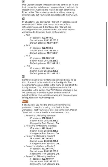
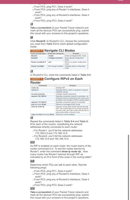
Use Copper Straight-I hrough cables to connect ail PCis to their respective switches and to connect each switch to its closest routec. Connect the routers to each other using Fiber cables. Your router connections will not come up automatically, but your switch connections to the PCs will. 3 . In Chapter 5, you configured PCs with IP addresses and subnet masks. Rofer back to that information for a refresher if you need it. Configure the PCs with the following information, and be sure to add notes to your workspace to document these configurations: a PC0: - IP address: 192.168.0.2 Subnet mask: 255.255.255.0 Default gatewayz 192.168.0.1 \& PC1 IP address: 192.168,0.3 Subnet mask: 255.255.255.0 Dofault gateway: 192.168.0.1 . PC2 - IP address: 192.168.10.2 - Subnet mask: 255.255.255.0 Default gateway: 192.168.10.1 aPC3 - IP address: 192.168.10.3 - Subnet mask: 255.255.255.0 - Default gaterway; 192.168.10.1 t. Configure each router's interfaces as listed below. To do this, click each router and click the Config tab. The network interfaces are listed in the menu on the left of the Config window. The LAN-facing inferface is the link connected to the switch. The WAN-facing interface is the link connected to another router. Be sure to make adjustments for your specific network and document your configurations in your workspace. NOE If at any point you need to check which interface a particular connection is using on a device, in the workspace, float your cursor over the connection. Packet Tracer will show the interface in use on each end. - RouterO's LAN-facing interface: - IP address: 192.168.0.1 - Subnet mask: 255.255.255.0 - Change the Port Status to On. b. Router0's WAN-facing interface: - IP address: 172.168.0.1 - Subnet mask 255.255.255.0 - Change the Port Status to On. -. Router1's interface to Router0: - IP adidress: 172.168.0.2 - Subnet mask: 255.255.255.0 - Change the Port Status to On. a Router1's interface to Router2: - IP address: 172.168.10.2 - Subnet mask: 255.255.255.0 - Change the Port Status to On. - Router2's LAN-facing interlace: - IP address: 192.168.10.1 - Subnet mask: 255.255.255.0 - Change the Port Status to On. . From PC0, ping PC1. Does it work? * From PCD, ping any of Routert's interlaces. Does it work? v. From PC0, ping any of Router2's interfaces. Does it work? a. From PCO, ping PC3. Does it work? big Take a screenshot of your Packel Tracer network and mark all the devices PCO can sucoessfully ping; submit this visual with your answers to this project's questions. In. Click Router0. In Router0's CLI, choose the commands you need from Table 94 to reach global configuration mode. marama Nastimata CII Mndae 3. In Router0's CLI, enter the commands listed in Table 9.5. Iablegm.5. Configure RIPv2 on Each 54 Repeat the commands listed in Table 9-4 and Table 95 for eoch of the routers, substituting the network addresses directly connected to each touter: - For Routert, you'll list the network addresses 172. 168.0.0 and 172.168.10.0. s For Router2, you'l list the network addresses 172.168.10.0 and 192.168.10.0. IO. As RIP is enabled on each router, the router leams of the roules connected to it. To see the roules leamed by Router1, enter the command show ip route rip. How many roules has Routert learned theough RIP, as indicated by an R in front of the route in the routing table? [1. Determine which PCs can talk to each other. Test the following pirigs: - From PCO, ping PC1. Does it work? s From PCO, ping any of RouterD's interfaces. Does it work? s. From PC0, ping any of Router2's interfaces, Does it work? a From PC0, ping PC3. Does it work? IV. Take a screenshot of your Packet Tracer network and mark all the devices PCO can successfully ping: submit. this visual with your answers to this project's questions. Use Copper Straight-I hrough cables to connect ail PCis to their respective switches and to connect each switch to its closest routec. Connect the routers to each other using Fiber cables. Your router connections will not come up automatically, but your switch connections to the PCs will. 3 . In Chapter 5, you configured PCs with IP addresses and subnet masks. Rofer back to that information for a refresher if you need it. Configure the PCs with the following information, and be sure to add notes to your workspace to document these configurations: a PC0: - IP address: 192.168.0.2 Subnet mask: 255.255.255.0 Default gatewayz 192.168.0.1 \& PC1 IP address: 192.168,0.3 Subnet mask: 255.255.255.0 Dofault gateway: 192.168.0.1 . PC2 - IP address: 192.168.10.2 - Subnet mask: 255.255.255.0 Default gateway: 192.168.10.1 aPC3 - IP address: 192.168.10.3 - Subnet mask: 255.255.255.0 - Default gaterway; 192.168.10.1 t. Configure each router's interfaces as listed below. To do this, click each router and click the Config tab. The network interfaces are listed in the menu on the left of the Config window. The LAN-facing inferface is the link connected to the switch. The WAN-facing interface is the link connected to another router. Be sure to make adjustments for your specific network and document your configurations in your workspace. NOE If at any point you need to check which interface a particular connection is using on a device, in the workspace, float your cursor over the connection. Packet Tracer will show the interface in use on each end. - RouterO's LAN-facing interface: - IP address: 192.168.0.1 - Subnet mask: 255.255.255.0 - Change the Port Status to On. b. Router0's WAN-facing interface: - IP address: 172.168.0.1 - Subnet mask 255.255.255.0 - Change the Port Status to On. -. Router1's interface to Router0: - IP adidress: 172.168.0.2 - Subnet mask: 255.255.255.0 - Change the Port Status to On. a Router1's interface to Router2: - IP address: 172.168.10.2 - Subnet mask: 255.255.255.0 - Change the Port Status to On. - Router2's LAN-facing interlace: - IP address: 192.168.10.1 - Subnet mask: 255.255.255.0 - Change the Port Status to On. . From PC0, ping PC1. Does it work? * From PCD, ping any of Routert's interlaces. Does it work? v. From PC0, ping any of Router2's interfaces. Does it work? a. From PCO, ping PC3. Does it work? big Take a screenshot of your Packel Tracer network and mark all the devices PCO can sucoessfully ping; submit this visual with your answers to this project's questions. In. Click Router0. In Router0's CLI, choose the commands you need from Table 94 to reach global configuration mode. marama Nastimata CII Mndae 3. In Router0's CLI, enter the commands listed in Table 9.5. Iablegm.5. Configure RIPv2 on Each 54 Repeat the commands listed in Table 9-4 and Table 95 for eoch of the routers, substituting the network addresses directly connected to each touter: - For Routert, you'll list the network addresses 172. 168.0.0 and 172.168.10.0. s For Router2, you'l list the network addresses 172.168.10.0 and 192.168.10.0. IO. As RIP is enabled on each router, the router leams of the roules connected to it. To see the roules leamed by Router1, enter the command show ip route rip. How many roules has Routert learned theough RIP, as indicated by an R in front of the route in the routing table? [1. Determine which PCs can talk to each other. Test the following pirigs: - From PCO, ping PC1. Does it work? s From PCO, ping any of RouterD's interfaces. Does it work? s. From PC0, ping any of Router2's interfaces, Does it work? a From PC0, ping PC3. Does it work? IV. Take a screenshot of your Packet Tracer network and mark all the devices PCO can successfully ping: submit. this visual with your answers to this project's questions 

Step by Step Solution
There are 3 Steps involved in it
Step: 1

Get Instant Access to Expert-Tailored Solutions
See step-by-step solutions with expert insights and AI powered tools for academic success
Step: 2

Step: 3

Ace Your Homework with AI
Get the answers you need in no time with our AI-driven, step-by-step assistance
Get Started


