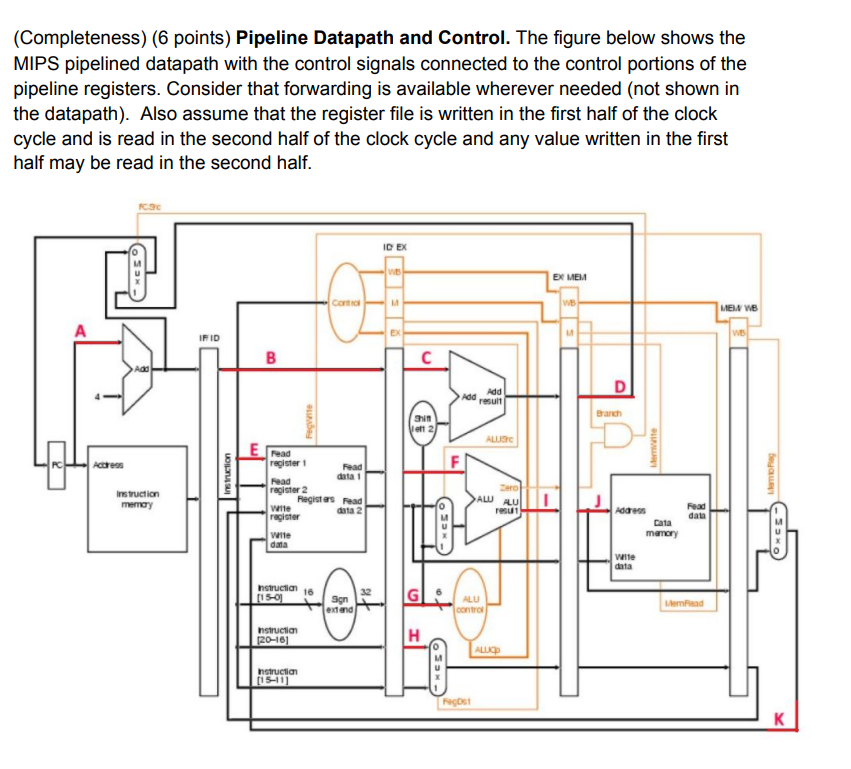
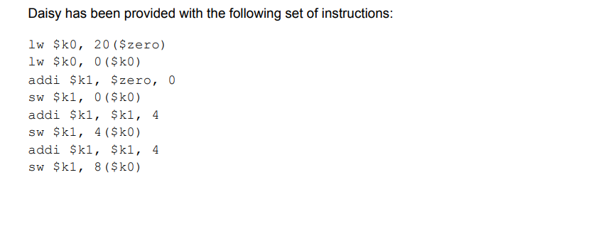
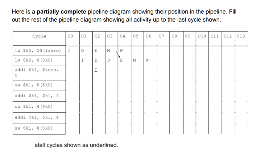
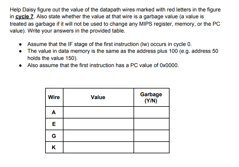
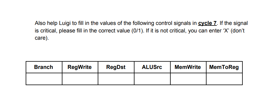
(Completeness) (6 points) Pipeline Datapath and Control. The figure below shows the MIPS pipelined datapath with the control signals connected to the control portions of the pipeline registers. Consider that forwarding is available wherever needed (not shown in the datapath). Also assume that the register file is written in the first half of the clock cycle and is read in the second half of the clock cycle and any value written in the first half may be read in the second half. CS ID EX WE EX MEM WE MENN WE FID WE B Add dre Branch egite Shin J2 ALLS Merite Instruction Menog Instruction memory Read register Read Read register 2 Registes Read Weite data 2 register wile data ALLU (OSO Fead data Address Data memory wile data instruction [150] 16 G Sign extend ALU control Lemad Instruction [20-161 H ALUQ SO Instruction [1541 Out K Daisy has been provided with the following set of instructions: lw $k0, 20 ($zero) lw $k0, 0 ($k0) addi $ki, $zero, O sw $ki, 0 ($0) addi ki, $ki, 4 sw $ki, 4 ($k0) addi $ki, $ki, 4 sw $ki, 8 ($0) Here is a partially complete pipeline diagram showing their position in the pipeline. Fill out the rest of the pipeline diagram showing all activity up to the last cycle shown. Cycle ci C2 C3 C4 C5 C6 C7 CB C9 ciocii C12C13 lw $t0, 20(Szero) 1 D E M w lw $K0, 0(SO) I D D M 2 addi $ki, Szero, SW $81, 0 (Sko) addi $ki, Ski, 4 sw $ki, 4 (Sko) addi $ki, Ski, 4 SW $ki, 8 (Sko) stall cycles shown as underlined. Help Daisy figure out the value of the datapath wires marked with red letters in the figure in cycle 7. Also state whether the value at that wire is a garbage value (a value is treated as garbage if it will not be used to change any MIPS register, memory, or the PC value). Write your answers in the provided table. Assume that the IF stage of the first instruction (lw) occurs in cycle 0. The value in data memory is the same as the address plus 100 (e.g. address 50 holds the value 150). Also assume that the first instruction has a PC value of 0x0000. Wire Value Garbage (Y/N) A E G K Also help Luigi to fill in the values of the following control signals in cycle 7. If the signal is critical, please fill in the correct value (0/1). If it is not critical, you can enter 'X' (don't care). Branch RegWrite RegDst ALUSrc MemWrite Mem ToReg (Completeness) (6 points) Pipeline Datapath and Control. The figure below shows the MIPS pipelined datapath with the control signals connected to the control portions of the pipeline registers. Consider that forwarding is available wherever needed (not shown in the datapath). Also assume that the register file is written in the first half of the clock cycle and is read in the second half of the clock cycle and any value written in the first half may be read in the second half. CS ID EX WE EX MEM WE MENN WE FID WE B Add dre Branch egite Shin J2 ALLS Merite Instruction Menog Instruction memory Read register Read Read register 2 Registes Read Weite data 2 register wile data ALLU (OSO Fead data Address Data memory wile data instruction [150] 16 G Sign extend ALU control Lemad Instruction [20-161 H ALUQ SO Instruction [1541 Out K Daisy has been provided with the following set of instructions: lw $k0, 20 ($zero) lw $k0, 0 ($k0) addi $ki, $zero, O sw $ki, 0 ($0) addi ki, $ki, 4 sw $ki, 4 ($k0) addi $ki, $ki, 4 sw $ki, 8 ($0) Here is a partially complete pipeline diagram showing their position in the pipeline. Fill out the rest of the pipeline diagram showing all activity up to the last cycle shown. Cycle ci C2 C3 C4 C5 C6 C7 CB C9 ciocii C12C13 lw $t0, 20(Szero) 1 D E M w lw $K0, 0(SO) I D D M 2 addi $ki, Szero, SW $81, 0 (Sko) addi $ki, Ski, 4 sw $ki, 4 (Sko) addi $ki, Ski, 4 SW $ki, 8 (Sko) stall cycles shown as underlined. Help Daisy figure out the value of the datapath wires marked with red letters in the figure in cycle 7. Also state whether the value at that wire is a garbage value (a value is treated as garbage if it will not be used to change any MIPS register, memory, or the PC value). Write your answers in the provided table. Assume that the IF stage of the first instruction (lw) occurs in cycle 0. The value in data memory is the same as the address plus 100 (e.g. address 50 holds the value 150). Also assume that the first instruction has a PC value of 0x0000. Wire Value Garbage (Y/N) A E G K Also help Luigi to fill in the values of the following control signals in cycle 7. If the signal is critical, please fill in the correct value (0/1). If it is not critical, you can enter 'X' (don't care). Branch RegWrite RegDst ALUSrc MemWrite Mem ToReg