Answered step by step
Verified Expert Solution
Question
1 Approved Answer
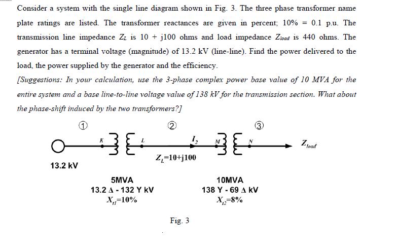
Consider a system with the single line diagram shown in Fig. 3. The three phase transformer name plate ratings are listed. The transformer reactances

Consider a system with the single line diagram shown in Fig. 3. The three phase transformer name plate ratings are listed. The transformer reactances are given in percent; 10% = 0.1 p.u. The transmission line impedance Zz is 10+ j100 ohms and load impedance Zload is 440 ohms. The generator has a terminal voltage (magnitude) of 13.2 kV (line-line). Find the power delivered to the load, the power supplied by the generator and the efficiency. [Suggestions: In your calculation, use the 3-phase complex power base value of 10 MVA for the entire system and a base line-to-line voltage value of 138 kV for the transmission section. What about the phase-shift induced by the two transformers?] 1 13.2 kV K 38 5MVA 13.2 A-132 Y KV X,-10% 1 Z-10+j100 Fig. 3 M E 10MVA 138 Y - 69 A KV X=8% 12 Zload
Step by Step Solution
★★★★★
3.32 Rating (152 Votes )
There are 3 Steps involved in it
Step: 1

Get Instant Access to Expert-Tailored Solutions
See step-by-step solutions with expert insights and AI powered tools for academic success
Step: 2

Step: 3

Ace Your Homework with AI
Get the answers you need in no time with our AI-driven, step-by-step assistance
Get Started


