Question
Consider ADDI instruction from LEGv8 ADDI X2, X1, #8 // Add 8 to X1 and store result in X2 The binary representation of this instruction
Consider ADDI instruction from LEGv8
ADDI X2, X1, #8 // Add 8 to X1 and store result in X2
The binary representation of this instruction is shown below
| opcode | Immediate | Rn | Rd |
10 bits 12 bits 5 bits 5bits
In the case of our example, Opcode = 1000000100 (10 bits)
Immediate = 0000 0000 1000 (12 bits)
Rn = 00001 (5 bits representing X1)
Rd = 00010 (5 bits representing X2)
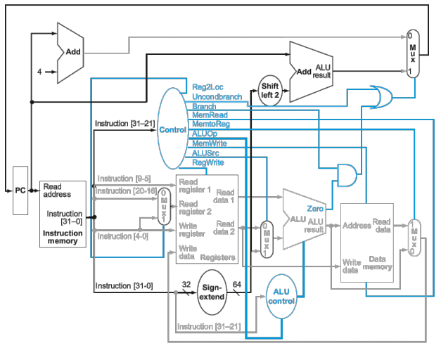
Show the values for all the control signals (each signal is either a zero or a one), and the ALU control (which ALU operation is executed).
For this (and most of the problems) we will use the datapaths and control paths shown on page 282 (figure 4.23)- also shown below.
Also, we will use the following for ALU control (to specify which operation is performed by the ALU
| ALU Control | Function |
| 0000 | AND |
| 0001 | OR |
| 0010 | add |
| 0110 | subtract |
| 0111 | pass input b |
| 1100 | NOR |

Step by Step Solution
There are 3 Steps involved in it
Step: 1

Get Instant Access to Expert-Tailored Solutions
See step-by-step solutions with expert insights and AI powered tools for academic success
Step: 2

Step: 3

Ace Your Homework with AI
Get the answers you need in no time with our AI-driven, step-by-step assistance
Get Started


