Answered step by step
Verified Expert Solution
Question
1 Approved Answer
Consider the diagram is shown in Figure Q4(c) where a packet filtering firewall (FW1) is running on router R2. The internal networks are on the
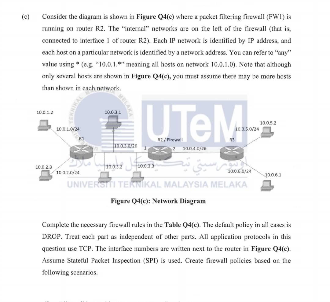
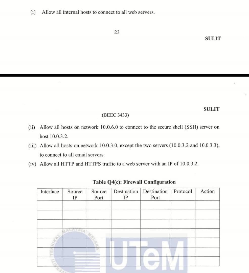
Consider the diagram is shown in Figure Q4(c) where a packet filtering firewall (FW1) is running on router R2. The "internal" networks are on the left of the firewall (that is, connected to interface 1 of router R2). Each IP network is identified by IP address, and each host on a particular network is identified by a network address. You can refer to "any" value using * (e.g. "10.0.1.*" meaning all hosts on network 10.0.1.0). Note that although only several hosts are shown in Figure Q4(c), you must assume there may be more hosts than shown in each network. Complete the necessary firewall rules in the Table Q4(c). The default policy in all cases is DROP. Treat each part as independent of other parts. All application protocols in this question use TCP. The interface numbers are written next to the router in Figure Q4(c). Assume Stateful Packet Inspection (SPI) is used. Create firewall policies based on the following scenarios. (i) Allow all internal hosts to connect to all web servers. 23 SULIT (BEEC 3433) SULIT (ii) Allow all hosts on network 10.0.6.0 to connect to the secure shell (SSH) server on host 10.0.3.2. (iii) Allow all hosts on network 10.0.3.0, except the two servers (10.0.3.2 and 10.0.3.3), to connect to all email servers. (iv) Allow all HTTP and HTTPS traffic to a web server with an IP of 10.0.3.2. Table Q4(c): Firewall Configuration
Step by Step Solution
There are 3 Steps involved in it
Step: 1
Get Instant Access to Expert-Tailored Solutions
See step-by-step solutions with expert insights and AI powered tools for academic success
Step: 2
Step: 3
Ace Your Homework with AI
Get the answers you need in no time with our AI-driven, step-by-step assistance
Get Started