Answered step by step
Verified Expert Solution
Question
1 Approved Answer
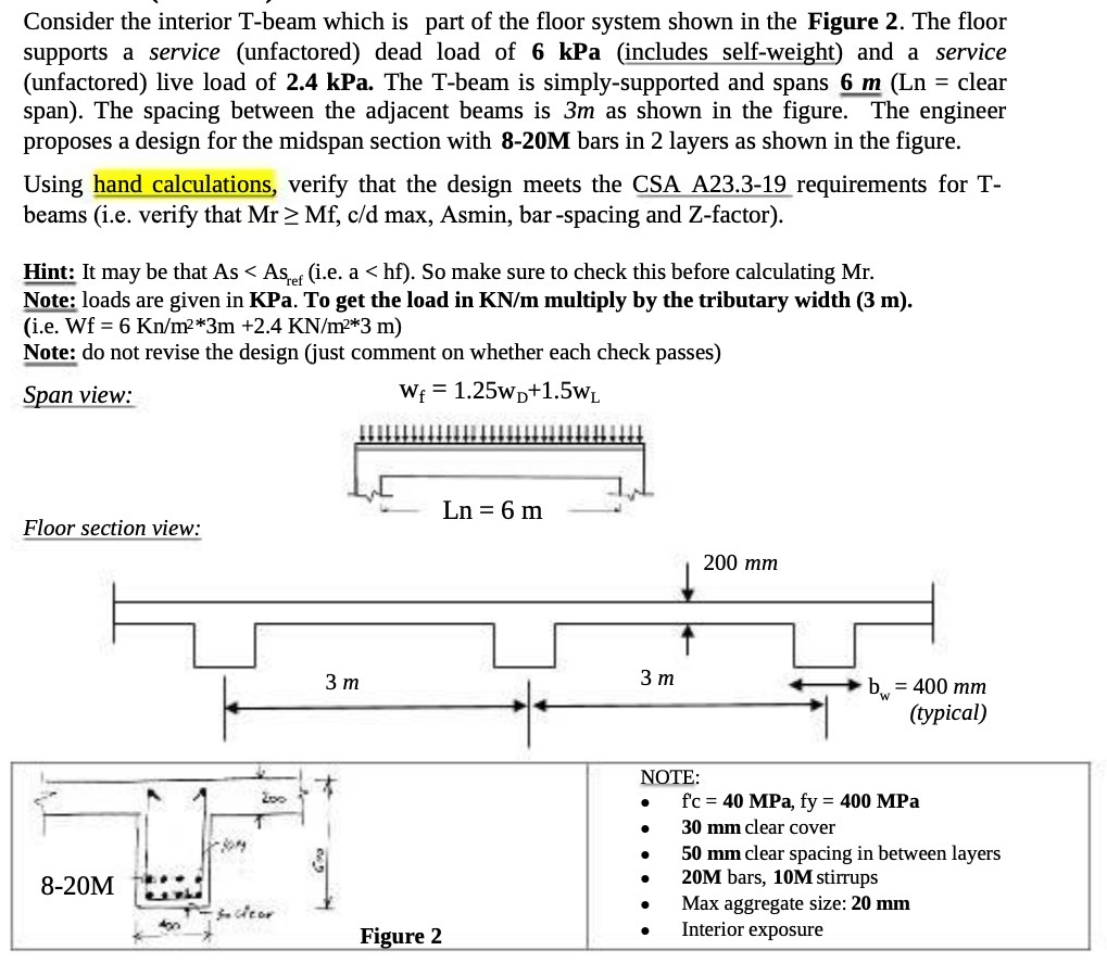
Consider the interior T-beam which is part of the floor system shown in the Figure 2. The floor supports a service (unfactored) dead load

Consider the interior T-beam which is part of the floor system shown in the Figure 2. The floor supports a service (unfactored) dead load of 6 kPa (includes self-weight) and a service (unfactored) live load of 2.4 kPa. The T-beam is simply-supported and spans 6 m (Ln = clear span). The spacing between the adjacent beams is 3m as shown in the figure. The engineer proposes a design for the midspan section with 8-20M bars in 2 layers as shown in the figure. Using hand calculations, verify that the design meets the CSA A23.3-19 requirements for T- beams (i.e. verify that Mr > Mf, c/d max, Asmin, bar-spacing and Z-factor). Hint: It may be that As < Asef (i.e. a < hf). So make sure to check this before calculating Mr. Note: loads are given in KPa. To get the load in KN/m multiply by the tributary width (3 m). (i.e. Wf 6 Kn/m*3m +2.4 KN/m*3 m) Note: do not revise the design (just comment on whether each check passes) Span view: Wf = 1.25WD+1.5WL Ln = 6 m Floor section view: 200 mm 8-20M 3 m 3 m b = 400 mm (typical) NOTE: 200 f'c 40 MPa, fy = 400 MPa 30 mm clear cover 50 mm clear spacing in between layers 20M bars, 10M stirrups -so clear Max aggregate size: 20 mm 400 Figure 2 Interior exposure
Step by Step Solution
There are 3 Steps involved in it
Step: 1

Get Instant Access to Expert-Tailored Solutions
See step-by-step solutions with expert insights and AI powered tools for academic success
Step: 2

Step: 3

Ace Your Homework with AI
Get the answers you need in no time with our AI-driven, step-by-step assistance
Get Started


