Question
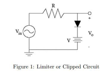
Consider the limiter circuit illustrated in Figure 1. Let R = 10k and V = 3.3V. Assume the diode has a 0.7 volt drop


Consider the limiter circuit illustrated in Figure 1. Let R = 10k and V = 3.3V. Assume the diode has a 0.7 volt drop across it when forward biased. For -5 Vin 5VDC, plot Vo versus Vin, being sure to label all important points in the plot. Now assume Vin is a 10 volt peak-to-peak 1kHz sine wave, plot Vin and Vo versus time on the same set of axes. Vin in R M V Vo Figure 1: Limiter or Clipped Circuit
Step by Step Solution
3.44 Rating (154 Votes )
There are 3 Steps involved in it
Step: 1

Get Instant Access to Expert-Tailored Solutions
See step-by-step solutions with expert insights and AI powered tools for academic success
Step: 2

Step: 3

Ace Your Homework with AI
Get the answers you need in no time with our AI-driven, step-by-step assistance
Get StartedRecommended Textbook for
Electric Machinery
Authors: Charles Kingsley, Jr, Stephen D. Umans
6th Edition
71230106, 9780073660097, 73660094, 978-0071230100
Students also viewed these Accounting questions
Question
Answered: 1 week ago
Question
Answered: 1 week ago
Question
Answered: 1 week ago
Question
Answered: 1 week ago
Question
Answered: 1 week ago
Question
Answered: 1 week ago
Question
Answered: 1 week ago
Question
Answered: 1 week ago
Question
Answered: 1 week ago
Question
Answered: 1 week ago
Question
Answered: 1 week ago
Question
Answered: 1 week ago
Question
Answered: 1 week ago
Question
Answered: 1 week ago
Question
Answered: 1 week ago
Question
Answered: 1 week ago
Question
Answered: 1 week ago
Question
Answered: 1 week ago
Question
Answered: 1 week ago
Question
Answered: 1 week ago
Question
Answered: 1 week ago
Question
Answered: 1 week ago
View Answer in SolutionInn App


