

Question: Consider the liquid-level control system shown in the diagram below. The tanks are noninteracting. We know that: -The resistances on the tanks are linear. These
Consider the liquid-level control system shown in the diagram below. The tanks are noninteracting. We know that: -The resistances on the tanks are linear. These resistances were tested separately, and it was found that, if the steady-state tank level h ft is plotted against steady state flow rate q cfm (cubic feet per minute), the slope of the line dh/dq is 0.5 min/ft^2. -The cross-sectional area of the first tank is 2 ft2 and that of the second tank is 4 ft^2. -The control valve was tested separately, and it was found that a change in 1 psi in pressure to the valve produced a change in flow of 0.1 cfm. -There is no dynamic lag in the valve or the measuring element. (a) Draw a block diagram of this control system and in each block give the transfer function, with numerical values of the parameters. Denote the outlet flow of the first tank as q1 and the liquid level of the second tank as h2. System variables and their units should be indicated on the block diagram. (b) Determine the controller gain [in units of psi/ft] for a critically damped closed-loop response. (c) Using 5 times the gain determined in part (b), determine the response of the level in tank 2 to a step change in the set point of 0.5 ft. What is the final steady-state
change in the tank level? Sketch the response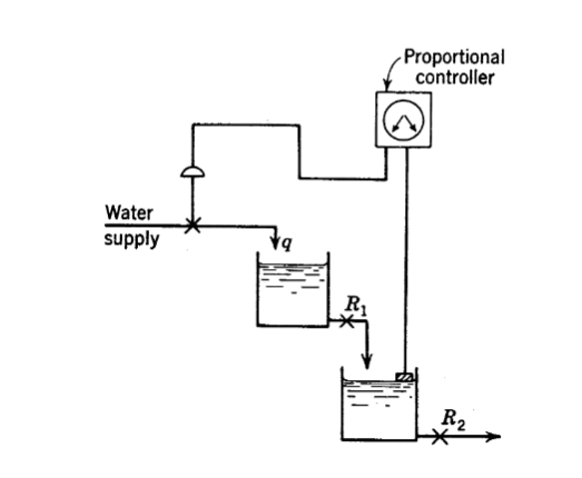
Proportional controller Water supply R; R2
Step by Step Solution
There are 3 Steps involved in it

Get step-by-step solutions from verified subject matter experts