Answered step by step
Verified Expert Solution
Question
1 Approved Answer
Consider the rock-crusher mechanism shown in Figures 1a and 1b, and complete the following: 1. Draw the kinematic diagram by hand or using the


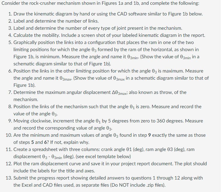
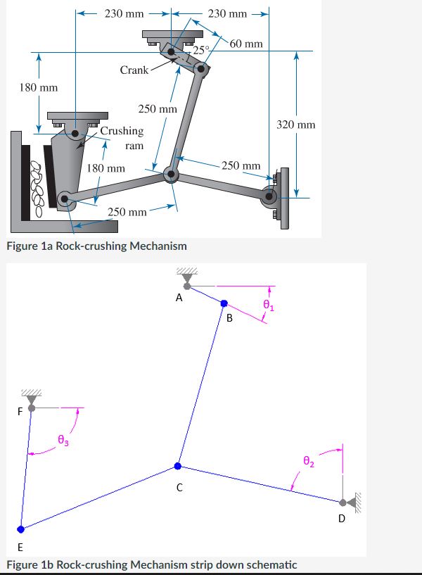
Consider the rock-crusher mechanism shown in Figures 1a and 1b, and complete the following: 1. Draw the kinematic diagram by hand or using the CAD software similar to Figure 1b below. 2. Label and determine the number of links. 3. Label and determine the number of every type of joint present in the mechanism. 4. Calculate the mobility. Include a screen shot of your labeled kinematic diagram in the report. 5. Graphically position the links into a configuration that places the ram in one of the two limiting positions for which the angle 03 formed by the ram of the horizontal, as shown in Figure 1b, is minimum. Measure the angle and name it 03min. (Show the value of 03min in a schematic diagram similar to that of Figure 1b). 6. Position the links in the other limiting position for which the angle 03 is maximum. Measure the angle and name it 03max. (Show the value of 03max in a schematic diagram similar to that of Figure 1b). 7. Determine the maximum angular displacement A03maxi also known as throw, of the mechanism. 8. Position the links of the mechanism such that the angle 0 is zero. Measure and record the value of the angle 03. 9. Moving clockwise, increment the angle 0 by 5 degrees from zero to 360 degrees. Measure and record the corresponding value of angle 03. 10. Are the minimum and maximum values of angle 03 found in step 9 exactly the same as those of steps 5 and 6? If not, explain why. 11. Create a spreadsheet with three columns: crank angle 01 (deg), ram angle 03 (deg), ram displacement 03 - 03min (deg). (see excel template below) 12. Plot the ram displacement curve and save it in your project report document. The plot should include the labels for the title and axes. 13. Submit the progress report showing detailed answers to questions 1 through 12 along with the Excel and CAD files used, as separate files (Do NOT include .zip files). 180 mm LL F 230 mm 03 Crank 250 mm Crushing ram 180 mm Figure 1a Rock-crushing Mechanism 250 mm A C 230 mm 25% 60 mm 250 mm B 320 mm 01 E Figure 1b Rock-crushing Mechanism strip down schematic 0 D /////
Step by Step Solution
There are 3 Steps involved in it
Step: 1

Get Instant Access to Expert-Tailored Solutions
See step-by-step solutions with expert insights and AI powered tools for academic success
Step: 2

Step: 3

Ace Your Homework with AI
Get the answers you need in no time with our AI-driven, step-by-step assistance
Get Started


