

Question: Consider the system shown in Figure 2 D(S) R(S) E(S) C(s) K G(S) Figure 2: Block diagram for Problem 2 2.1- (20 pts) Sketch a
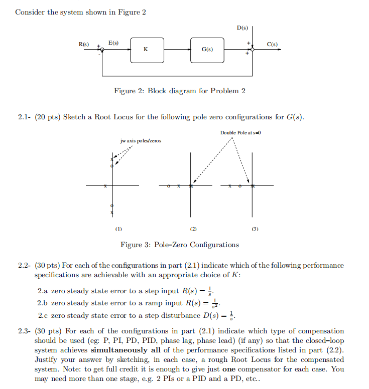
Consider the system shown in Figure 2 D(S) R(S) E(S) C(s) K G(S) Figure 2: Block diagram for Problem 2 2.1- (20 pts) Sketch a Root Locus for the following pole zero configurations for G(s). Double Pole at s=0 jw axis poles/zeros F (1) (2) (3) Figure 3: Pole-Zero Configurations 2.2- (30 pts) For each of the configurations in part (2.1) indicate which of the following performance specifications are achievable with an appropriate choice of K: 2.a zero steady state error to a step input R(s) = 2.b zero steady state error to a ramp input R(s) = 2.c zero steady state error to a step disturbance D(s) = 2.3- (30 pts) For each of the configurations in part (2.1) indicate which type of compensation should be used (eg: P, PI, PD, PID, phase lag, phase lead) (if any) so that the closed-loop system achieves simultaneously all of the performance specifications listed in part (2.2). Justify your answer by sketching, in each case, a rough Root Locus for the compensated system. Note: to get full credit it is enough to give just one compensator for each case. You may need more than one stage, e.g. 2 PIs or a PID and a PD, etc
Step by Step Solution
There are 3 Steps involved in it

Get step-by-step solutions from verified subject matter experts