Question
Could I please have the worked solution for the question as follows: a) Using the bilinear transform method determine the pulse transfer function, G(z), of
Could I please have the worked solution for the question as follows:
a) Using the bilinear transform method determine the pulse transfer function, G(z), of a digital notch filter i.e. a narrow band reject filter, starting from an analogue filter described by the transfer function:

The filter should have a zero amplitude response at a frequency of 50 Hz and a sampling period, T = 1/200 seconds, i.e. a sampling frequency, fs = 200 Hz.

b) From G(z) derive the linear difference equation for the filter and draw in block diagram form a possible physical realization of the filter.
c) Sketch the zero location in the z-plane and from this show that the digital filter has a zero amplitude response at a frequency of 50 Hz.
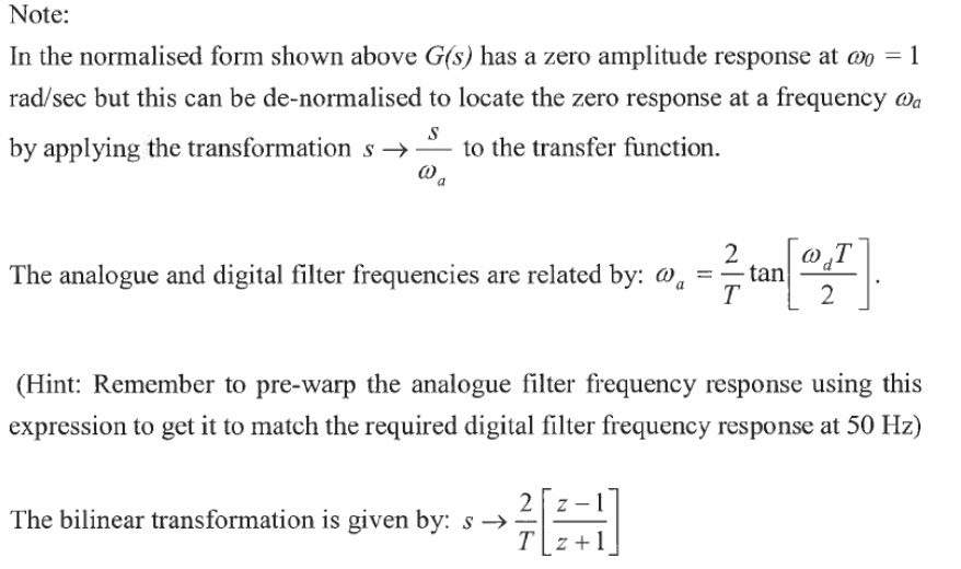
In the normalised form shown above G(s) has a zero amplitude response at 0=1 rad/sec but this can be de-normalised to locate the zero response at a frequency a by applying the transformation sas to the transfer function. The analogue and digital filter frequencies are related by: a=T2tan[2dT]. (Hint: Remember to pre-warp the analogue filter frequency response using this expression to get it to match the required digital filter frequency response at 50Hz ) The bilinear transformation is given by: sT2[z+1z1]
Step by Step Solution
There are 3 Steps involved in it
Step: 1

Get Instant Access to Expert-Tailored Solutions
See step-by-step solutions with expert insights and AI powered tools for academic success
Step: 2

Step: 3

Ace Your Homework with AI
Get the answers you need in no time with our AI-driven, step-by-step assistance
Get Started


