Create a lab report for Ohm's Law. I will provide the material and instructions: Ohm's Law Ohm's law states that if a conductor is kept
Create a lab report for Ohm's Law. I will provide the material and instructions:
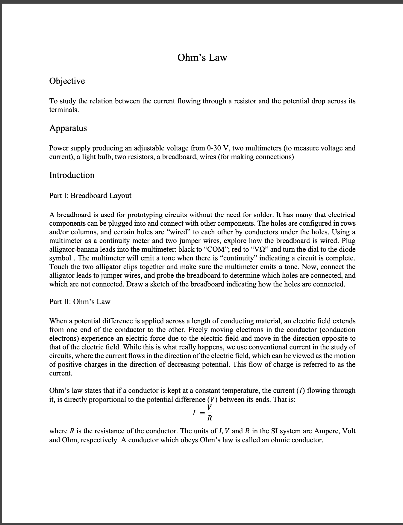
Ohm's Law
Ohm's law states that if a conductor is kept at a constant temperature, the current (?) flowing through it, is directly proportional to the potential difference (?) between its ends. That is:
? =?/?
where ? is the resistance of the conductor. The units of ?,? and ? in the SI system are Ampere, Volt and Ohm, respectively. A conductor which obeys Ohm's law is called an ohmic conductor.
Read the information in the experimental procedure carefully
Plot graphs for each component (You can have them in a one graph)
Calculate the resistance for linear resistances.
Lab report must include:
Purpose and Theory- A concise description about purpose of the lab and related theory (Ex. Ohm's law and circuit diagram)
Procedure- Include a summary of the lab procedure in your words (don't repeat the given lab procedure again).
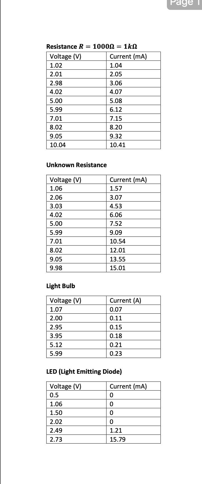
Data- you may include the data tables.
Data Analysis/Calculations/Graphs - Complete the graphs and calculations.
Error Analysis- Do the percentage error analysis (if possible)
Discussion and Conclusion - Answer to the questions (if you have any). Discuss about the experiment.
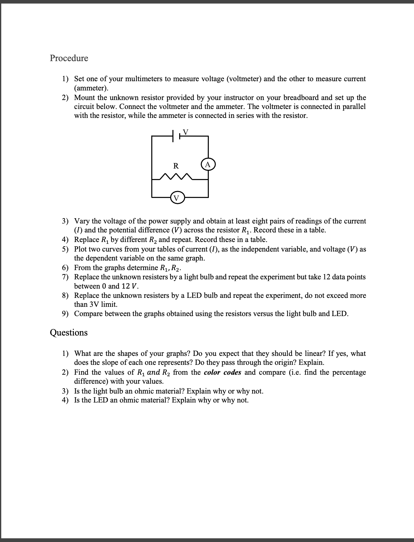
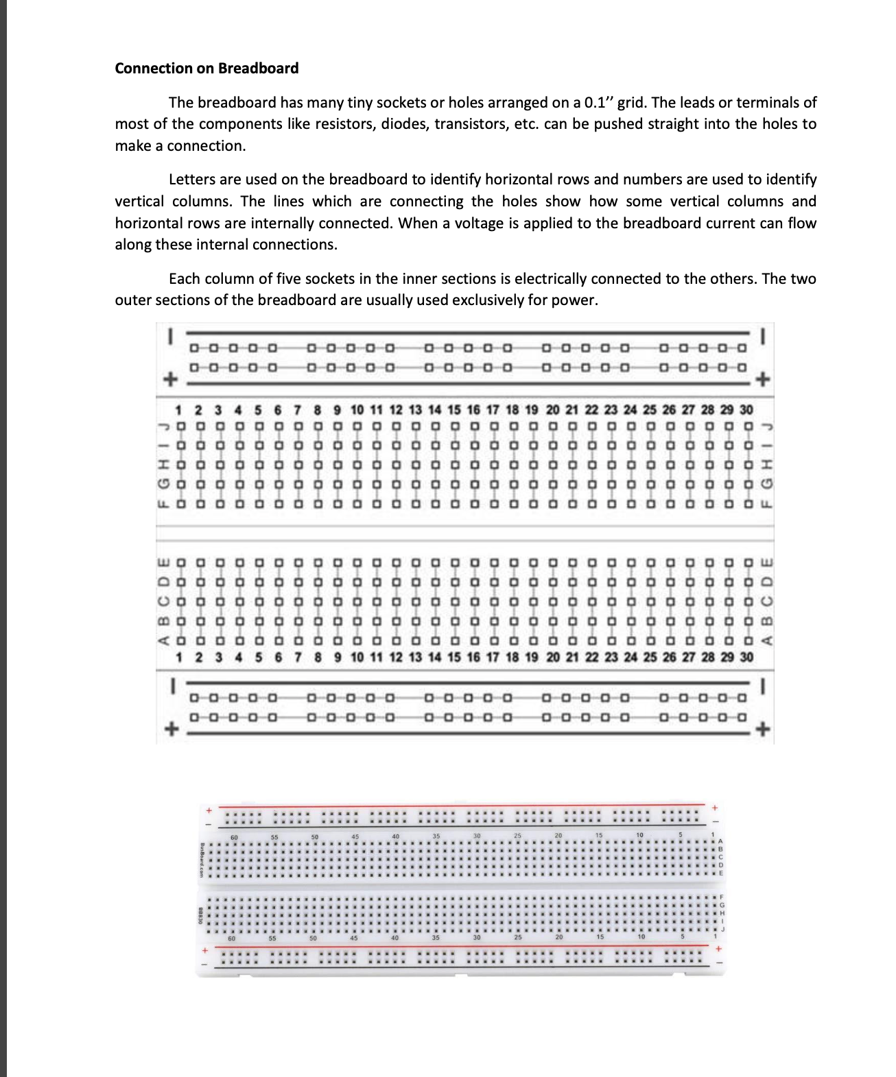
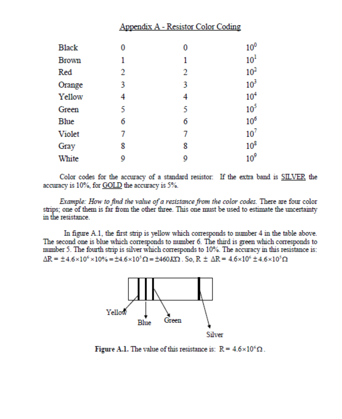
Ohm's Law (ecve To study the relation between the current owing through a resistor and the potential drop across its terminals. .Appanuus Power supply producing an adjustable voltage from 030 V, two multimeters (to measure voltage and current), a light bulb, two resistors, a breadboard, wires (for making connections) Innoducon Part I: Breadboard Layout A breadboard is used for prototyping circuits without the need for solder. It has many that electrical components can be plugged into and connect with other components. The holes are congured in rows andfor columns, and certain holes are \"wired\" to each other by conductors under the holes. Using a multimeter as a continuity meter and two jumper wires, explore how the breadboard is wired. Plug alligatorbanana leads into the multimeter: black to \"COM\"; red to \"V9\" and turn the dial to the diode symbol . The multimeter will emit a tone when there is \"continuity" indicating a circuit is complete. Touch the two alligator clips together and make sure the multimeter emits a tone. Now, connect the alligator leads to jumper wires, and probe the breadboard to determine which holes are connected, and which are not connected. Draw a sketch of the breadboard indicating how the holes are connected. Part II: Ohm's Law When a potential difference is applied across a length of conducting material, an electric field extends from one end of the conductor to the other. Freely moving electrons in the conductor (conduction electrons) experience an electric force due to the electric eld and move in the direction opposite to that of the electric eld. While this is what really happens, we use conventional current in the study of circuits, where the current flows in the direction of the electric eld, which can be viewed as the motion of positive charges in the direction of decreasing potential. This ow of charge is referred to as the current. Ohm's law states that if a conductor is kept at a constant temperature, the current (I) owing through it, is directly proportional to the potential difference (V) between its ends. That is: V I = R where R is the resistance of the conductor. The units of I, V and R in the SI system are Ampere, Volt and Ohm, respectively. A conductor which obeys Ohm's law is called an ohmic conductor. Procedure 1) 2) 3) 4) 5) 6) 7) 8) 9) Set one of your multimeters to measure voltage (voltmeter) and the other to measure current (ammeter). Mount the unknown resistor provided by your instructor on your breadboard and set up the circuit below. Connect the voltmeter and the ammeter. The voltmeter is connected in parallel with the resistor, while the arnmeter is connected in series with the resistor. Vary the voltage of the power supply and obtain at least eight pairs of readings of the current (I) and the potential difference (V) across the resistor R1. Record these in a table. Replace R1 by different R2 and repeat. Record these in a table. Plot two curves from your tables of current (I), as the independent variable, and voltage (V) as the dependent variable on the same graph. From the graphs determine R1, R2. Replace the unknown resisters by a light bulb and repeat the experiment but take 12 data points between 0 and 12 V. Replace the unknown resisters by a LED bulb and repeat the experiment, do not exceed more than 3V limit. Compare between the graphs obtained using the resistors versus the light bulb and LED. Questions 1) 2) 3) 4) What are the shapes of your graphs? Do you expect that they should be linear? If yes, what does the slope of each one represents? Do they pass through the origin? Explain. Find the values of R1 and R2 from the color codes and compare (i.e. nd the percentage difference) with your values. Is the light bulb an ohmic material? Explain why or why not. Is the LED an ohmic material? Explain why or why not. Resistance R = 10009 = 1M). Voltage (V) Current (mA) 1.02 1.04 2.01 2.05 2.98 3.05 4.02 4.07 5.00 5.08 5.99 5.12 7.01 7.15 8.02 8.20 | 9.05 9.32 | 10.04 10.41 Unknown Resistance I Voltage (V) Current (mA) | 1.05 1.57 | 2.05 3.07 | 3.03 4.53 4.02 5.05 5.00 7.52 5.99 9.09 7.01 10.54 8.02 12.01 9.05 13.55 | 9.98 15.01 Light Bulb Voltage (V) Current (A) 1.07 0.07 2.00 0.11 2.95 0.15 3.95 0.18 5.12 0.21 5.99 0.23 LED (Light Emitting Diode) Voltage (V) Current (mA) 0.5 0 1.05 0 1.50 0 2.02 0 2.49 1.21 2.73 15.79 Connection on Breadboard The breadboard has many tiny sockets or holes arranged on a 0.1" grid. The leads or terminals of most of the components like resistors, diodes, transistors, etc. can be pushed straight into the holes to make a connection Letters are used on the breadboard to identify horizontal rows and numbers are used to identify vertical columns. The lines which are connecting the holes show how some vertical columns and horizontal rows are internally connected. When a voltage is applied to the breadboard current can flow along these internal connections. Each column of five sockets in the inner sections is electrically connected to the others. The two outer sections of the breadboard are usually used exclusively for power. DO000 0 0 0 0 0 0 0 0 0 0 00000 000 0 0 0000 0 0 0 0 0 0 2 3 4 5 6 7 8 9 10 11 12 13 14 15 16 17 18 19 20 21 22 23 24 25 26 27 28 29 30 DOO O- o 3 0-0 ABCDE DO0 00 DO0 00 0 0 0 0-0 0 0 0 0 0 DO00 0 B un D 10 11 12 13 14 15 16 17 18 19 20 21 22 23 24 25 26 27 28 29 30 DO0 0 0 0 0 0 0 0 0 0 0 0 0 DO000 0000 0 0 0 0 00 00 0 0 0 0 0 0 0 0 0 0 0 0 0 .+ 1 . . . ..Appendix A - Resistor Color Coding Black 100 Brown 101 Red 102 Orange 103 Yellow 104 DO NOVAWNHO DONOUAWNEO Green 10 Blue 106 Violet 10' Gray 108 White 109 Color codes for the accuracy of a standard resistor. If the extra band is SILVER the accuracy is 10%, for GOLD the accuracy is 5%. Example: How to find the value of a resistance from the color codes. There are four color strips; one of them is far from the other three. This one must be used to estimate the uncertainty in the resistance. In figure A.1, the first strip is yellow which corresponds to number 4 in the table above. The second one is blue which corresponds to number 6. The third is green which corresponds to munber 5. The fourth strip is silver which corresponds to 10%. The accuracy in this resistance is: AR = 14.6x105 x10% =14.6x10'n=$460X2 . So, R # AR = 4.6x10 +4.6x10'n Yellow Blue Green Silver Figure A.1. The value of this resistance is: R = 4.6x10502
Step by Step Solution
There are 3 Steps involved in it
Step: 1
Get Instant Access to Expert-Tailored Solutions
See step-by-step solutions with expert insights and AI powered tools for academic success
Step: 2
Step: 3
Ace Your Homework with AI
Get the answers you need in no time with our AI-driven, step-by-step assistance