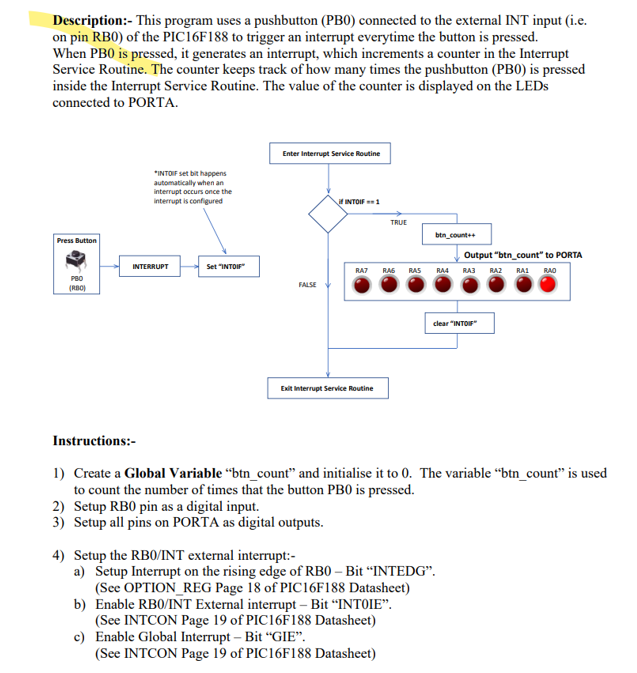
Description:- This program uses a pushbutton (PB0) connected to the external INT input (i.e. on pin RB0) of the PIC16F188 to trigger an interrupt everytime the button is pressed. When PB0 is pressed, it generates an interrupt, which increments a counter in the Interrupt Service Routine. The counter keeps track of how many times the pushbutton (PB0) is pressed inside the Interrupt Service Routine. The value of the counter is displayed on the LEDs connected to PORTA. Instructions:- 1) Create a Global Variable "btn_count" and initialise it to 0. The variable "btn_count" is used to count the number of times that the button PB0 is pressed. 2) Setup RB0 pin as a digital input. 3) Setup all pins on PORTA as digital outputs. 4) Setup the RB0/INT external interrupt:- a) Setup Interrupt on the rising edge of RB0 - Bit "INTEDG". (See OPTION_REG Page 18 of PIC16F188 Datasheet) b) Enable RB0/INT External interrupt - Bit "INT0IE". (See INTCON Page 19 of PIC16F188 Datasheet) c) Enable Global Interrupt - Bit "GIE". (See INTCON Page 19 of PIC16F188 Datasheet) 5) In main(), leave an empty while(1) loop as all the functionaility will be contained in the Interrupt Service Routine (ISR). 6) Create an Interrupt Service Routine(ISR):- a) Use function header for ISR:- void _ interrupt() isr(void) b) Inside the ISR i. Check if the INT0IF flag has been set (Page 19 PIC16F188 Datasheet) ii. If INTOIF flag if set, increment "btn_count" variable. iii. Use the variable "btn_count" to directly drive the LEDs connected to PORTA. iv. Reset the INTOIF flag 7) At this point, you should have a working program that functions as descried in the description section above. Simulate the program in Proteus to ensure that it works as it should. 8) Toggle the value of the "INTEDG" bit and record your observations in a Microsoft Word file that you submit along with the Proteus exercises within the Zip file. Name the Word File "Exercise_4_Answers.doc". As an example list your observation as follows:- ANS: EX_4_1_Part_8 After adjusting the INTEDG bit...... 9) Inside the ISR:- 1) Put the value of INTEDG back to its original value, before Step 8. Comment out where you reset the INT0IF flag. (2) Insert a delay of 50mSec inside the ISR to observe the result of not resetting the INT0IF flag. Record the effect of not resetting the INT0IF flag and state the reason for the observed effect in the Microsoft Word file that you created above. As an example list your observation as follows:- ANS: EX_4_1_Part_9 The result of not resetting the INTOIF flag,...... 10) Return the code to a working state (i.e. end of Step 7 above). Download the code to the PIC development board using the PPP programmer. Ensure the LEDs are connected to PORTA whith the switches connected to PORTB. What non-ideal behavour do you notice on real hardware? State your answer in the Microsoft Word File ANS: EX_4_1_Part_10 Inputs:-1 (i.c. RB0))