Answered step by step
Verified Expert Solution
Question
1 Approved Answer
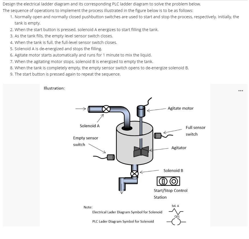
Design the electrical ladder diagram and its corresponding PLC ladder diagram to solve the problem below. The sequence of operations to implement the process

Design the electrical ladder diagram and its corresponding PLC ladder diagram to solve the problem below. The sequence of operations to implement the process illustrated in the figure below is to be as follows: 1. Normally open and normally closed pushbutton switches are used to start and stop the process, respectively. Initially, the tank is empty. 2. When the start button is pressed, solenoid A energizes to start filling the tank. 3. As the tank fills, the empty level sensor switch closes. 4. When the tank is full, the full-level sensor switch closes. 5. Solenoid A is de-energized and stops the filling. 6. Agitate motor starts automatically and runs for 1 minute to mix the liquid. 7. When the agitating motor stops, solenoid B is energized to empty the tank. 8. When the tank is completely empty, the empty sensor switch opens to de-energize solenoid B. 9. The start button is pressed again to repeat the sequence. Illustration: Solenoid A Empty sensor switch Note: Agitate motor Electrical Lader Diagram Symbol for Solenoid PLC Lader Diagram Symbol for Solenoid Agitator Solenoid B OO Start/Stop Control Station Full sensor switch Sol. A Q01
Step by Step Solution
★★★★★
3.38 Rating (151 Votes )
There are 3 Steps involved in it
Step: 1
Explanation Input Start PBNO 100 Stop PBNC 101 Full level sensorNO 102 Empty level sensor N...
Get Instant Access to Expert-Tailored Solutions
See step-by-step solutions with expert insights and AI powered tools for academic success
Step: 2

Step: 3

Ace Your Homework with AI
Get the answers you need in no time with our AI-driven, step-by-step assistance
Get Started


