Answered step by step
Verified Expert Solution
Question
1 Approved Answer
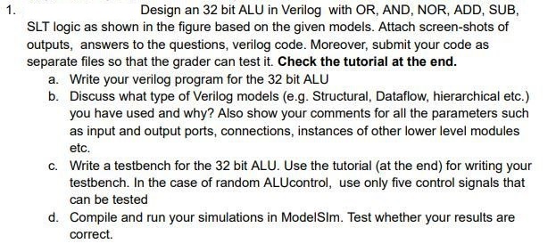
Design an 3 2 bit ALU in Verilog with OR , AND, NOR, ADD, SUB, SLT logic as shown in the figure based on the
Design an bit ALU in Verilog with OR AND, NOR, ADD, SUB,
SLT logic as shown in the figure based on the given models. Attach screenshots of
outputs, answers to the questions, verilog code. Moreover, submit your code as
separate files so that the grader can test it Check the tutorial at the end.
a Write your verilog program for the bit ALU
b Discuss what type of Verilog models eg Structural, Dataflow, hierarchical etc.
you have used and why? Also show your comments for all the parameters such
as input and output ports, connections, instances of other lower level modules
etc.
c Write a testbench for the bit ALU. Use the tutorial at the end for writing your
testbench. In the case of random ALUcontrol, use only five control signals that
can be tested
d Compile and run your simulations in ModelSIm. Test whether your results are
correct.

Step by Step Solution
There are 3 Steps involved in it
Step: 1

Get Instant Access to Expert-Tailored Solutions
See step-by-step solutions with expert insights and AI powered tools for academic success
Step: 2

Step: 3

Ace Your Homework with AI
Get the answers you need in no time with our AI-driven, step-by-step assistance
Get Started


