

Answered step by step
Verified Expert Solution
Question
1 Approved Answer
design Design a circuit for the criteria given below. The designed circuit will turn on either green or red LED shown on the right depending
design
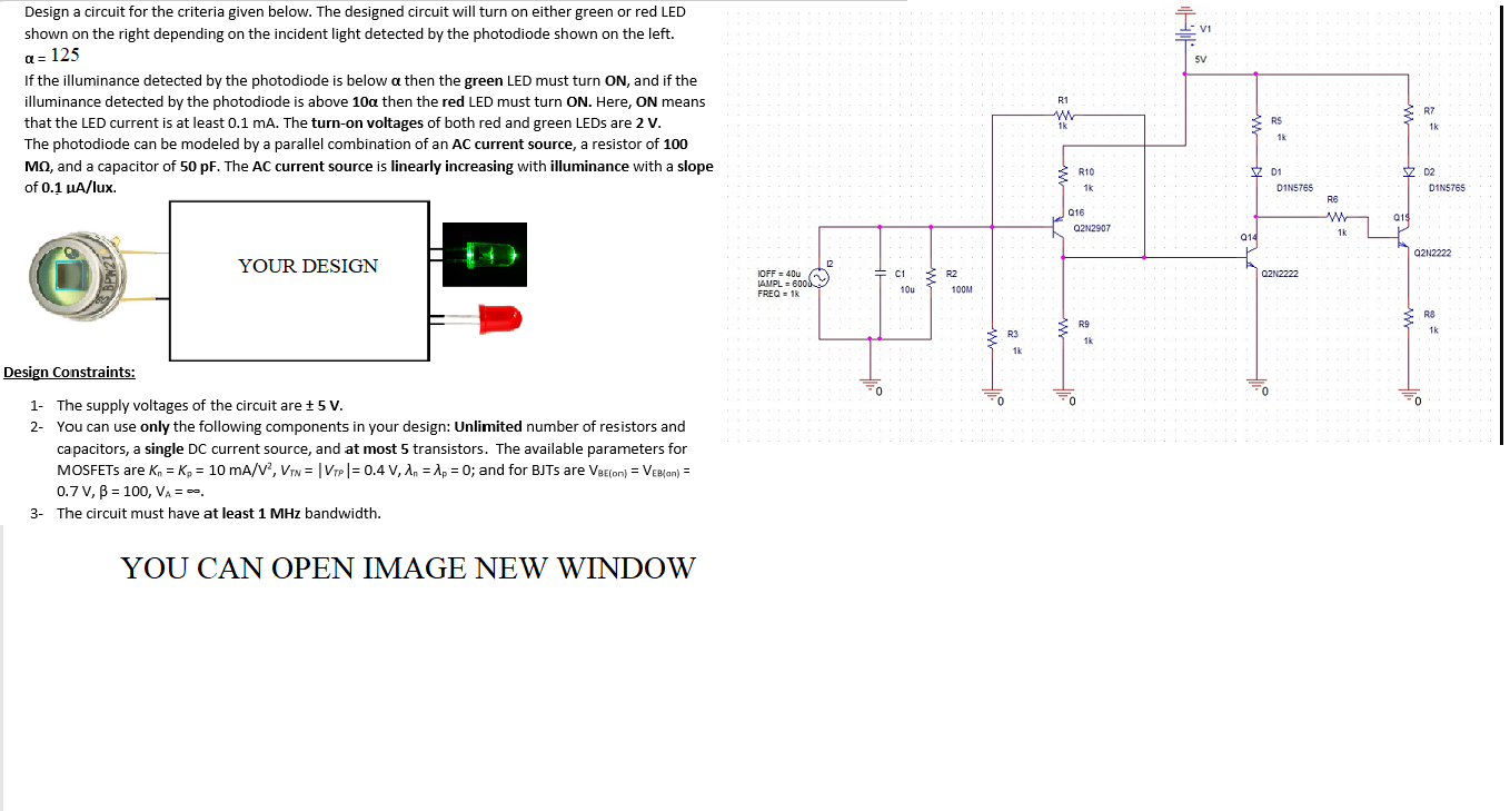
Design a circuit for the criteria given below. The designed circuit will turn on either green or red LED shown on the right depending on the incident light detected by the photodiode shown on the left. V1 a = 125 SV R1 W 1k R7 RS 1k If the illuminance detected by the photodiode is below a then the green LED must turn ON, and if the illuminance detected by the photodiode is above 100 then the red LED must turn ON. Here, ON means that the LED current is at least 0.1 mA. The turn-on voltages of both red and green LEDs are 2 V. The photodiode can be modeled by a parallel combination of an AC current source, a resistor of 100 MO, and a capacitor of 50 pF. The AC current source is linearly increasing with illuminance with a slope of 0.1 A/lux 1k R10 1k V D1 D1N5765 Z D2 D1N5765 RB Q16 Q2N2907 w 019 014 1k Q2N2222 YOUR DESIGN 2 c1 R2 O2N2222 IOFF = 40 IAMPL = 6000 FREQ - 1 10u 100M R9 RS 1k R3 1k 1k Design Constraints: 0 0 0 0 1- The supply voltages of the circuit are + 5 V. 2- You can use only the following components in your design: Unlimited number of resistors and capacitors, a single DC current source, and at most 5 transistors. The available parameters for MOSFETs are kn = K = 10 mA/V2, VTN = | VTP |= 0.4 V, 1.. = 1p = 0; and for BJTs are VeEcon} = Vee/an) = 0.7V, B = 100, VA= . 3- The circuit must have at least 1 MHz bandwidth. YOU CAN OPEN IMAGE NEW WINDOW Design a circuit for the criteria given below. The designed circuit will turn on either green or red LED shown on the right depending on the incident light detected by the photodiode shown on the left. V1 a = 125 SV R1 W 1k R7 RS 1k If the illuminance detected by the photodiode is below a then the green LED must turn ON, and if the illuminance detected by the photodiode is above 100 then the red LED must turn ON. Here, ON means that the LED current is at least 0.1 mA. The turn-on voltages of both red and green LEDs are 2 V. The photodiode can be modeled by a parallel combination of an AC current source, a resistor of 100 MO, and a capacitor of 50 pF. The AC current source is linearly increasing with illuminance with a slope of 0.1 A/lux 1k R10 1k V D1 D1N5765 Z D2 D1N5765 RB Q16 Q2N2907 w 019 014 1k Q2N2222 YOUR DESIGN 2 c1 R2 O2N2222 IOFF = 40 IAMPL = 6000 FREQ - 1 10u 100M R9 RS 1k R3 1k 1k Design Constraints: 0 0 0 0 1- The supply voltages of the circuit are + 5 V. 2- You can use only the following components in your design: Unlimited number of resistors and capacitors, a single DC current source, and at most 5 transistors. The available parameters for MOSFETs are kn = K = 10 mA/V2, VTN = | VTP |= 0.4 V, 1.. = 1p = 0; and for BJTs are VeEcon} = Vee/an) = 0.7V, B = 100, VA= . 3- The circuit must have at least 1 MHz bandwidth. YOU CAN OPEN IMAGE NEW WINDOW Step by Step Solution
There are 3 Steps involved in it
Step: 1

Get Instant Access to Expert-Tailored Solutions
See step-by-step solutions with expert insights and AI powered tools for academic success
Step: 2

Step: 3
Ace Your Homework with AI
Get the answers you need in no time with our AI-driven, step-by-step assistance
Get Started
Justified The Story Of Americas Audit
Authors: Dr. Kelli Ward
1st Edition
195725503X, 978-1957255033