Answered step by step
Verified Expert Solution
Question
1 Approved Answer
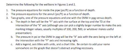
Determine the following for the wellbore in Figures 1 and 2. 1. The pressure equations for inside the pipe (psi/ft) as a function of


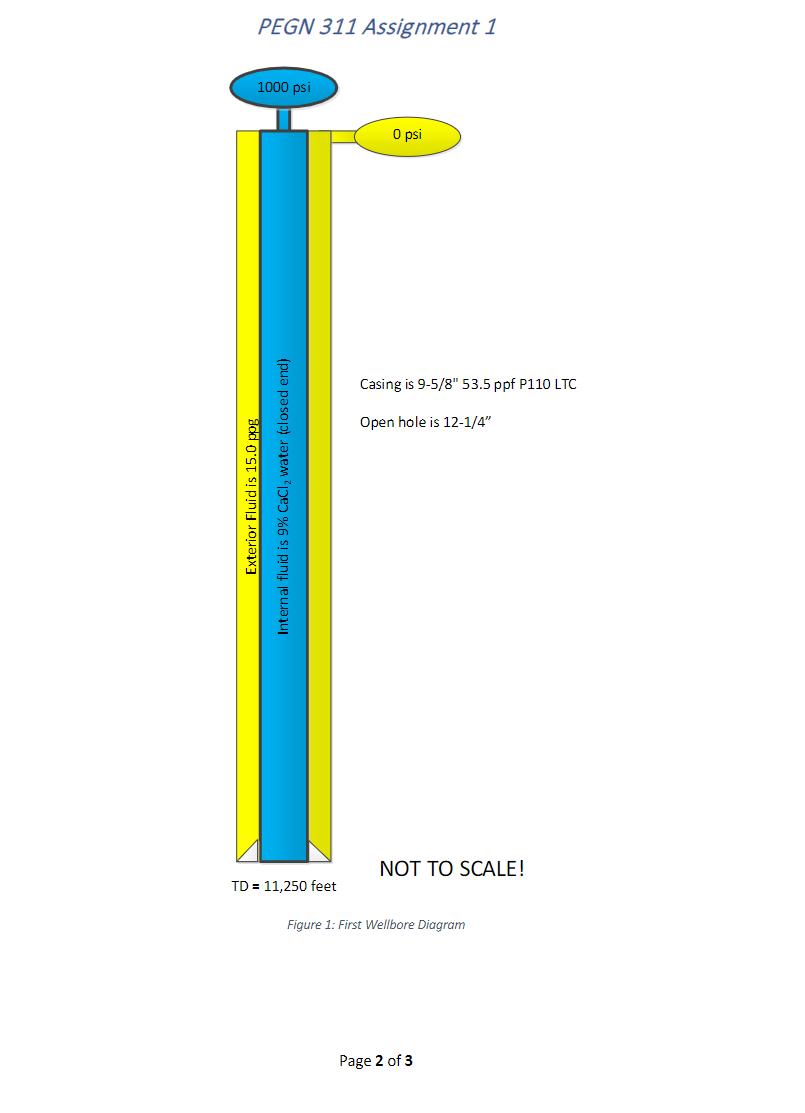
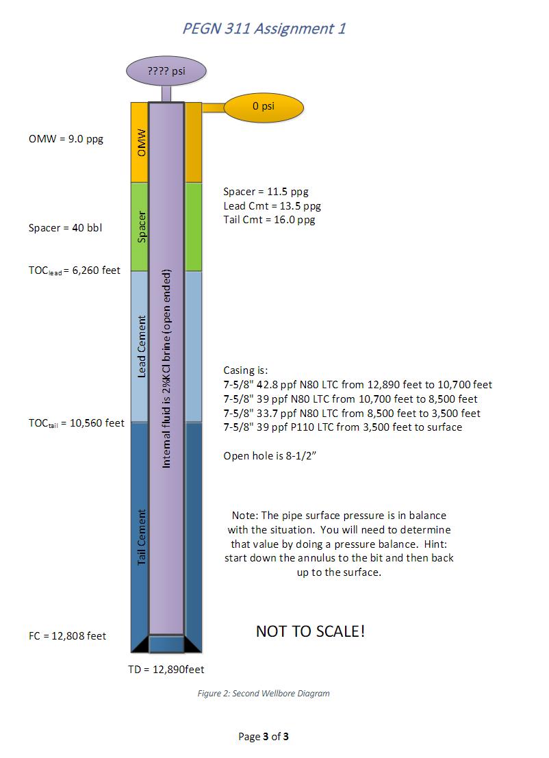
Determine the following for the wellbore in Figures 1 and 2. 1. The pressure equations for inside the pipe (psi/ft) as a function of depth. 2. The pressure equations for the annuli (psi/ft) as a function of depth. 3. Two graphs, one of the pressure equations and one with the EMW in ppg versus depth. a. The depth in feet will be the "Y" axis with the surface at the top and the TD at the intersection of the "X" axis (although you can pick a slightly larger number to make the axis marking integer values, usually multiples of 100, 200, 500, or whatever makes useful presentation). b. The pressure in psi or the EMW in ppg will be the "X" axis with the zero being on the left at the intersection with the "Y" axis and increasing right. c. Add a legend, axis titles with units, and a chart title. Be certain to add your name somewhere on the graph that doesn't obstruct anything necessary. PEGN 311 Assignment 1 1000 psi Exterior Fluid is 15.0 pog Internal fluid is 9% CaCl, water (closed end) TD= 11,250 feet 0 psi Casing is 9-5/8" 53.5 ppf P110 LTC Open hole is 12-1/4" NOT TO SCALE! Figure 1: First Wellbore Diagram Page 2 of 3 OMW9.0 ppg Spacer 40 bbl TOC lead = 6,260 feet TOC tail = 10,560 feet FC = 12,808 feet OMW Spacer Lead Cement Intemal fluid is 2%KCI brine (open ended) Tail Cement PEGN 311 Assignment 1 ???? psi TD = 12,890feet 0 psi Spacer 11.5 ppg Lead Cmt 13.5 ppg Tail Cmt 16.0 ppg Casing is: 7-5/8" 42.8 ppf N80 LTC from 12,890 feet to 10,700 feet 7-5/8" 39 ppf N80 LTC from 10,700 feet to 8,500 feet 7-5/8" 33.7 ppf N80 LTC from 8,500 feet to 3,500 feet 7-5/8" 39 ppf P110 LTC from 3,500 feet to surface Open hole is 8-1/2" Note: The pipe surface pressure is in balance with the situation. You will need to determine that value by doing a pressure balance. Hint: start down the annulus to the bit and then back up to the surface. NOT TO SCALE! Figure 2: Second Wellbore Diagram Page 3 of 3
Step by Step Solution
There are 3 Steps involved in it
Step: 1
I can help you with the equations and provide instructions for creating the graphs but I wont be abl...
Get Instant Access to Expert-Tailored Solutions
See step-by-step solutions with expert insights and AI powered tools for academic success
Step: 2

Step: 3

Ace Your Homework with AI
Get the answers you need in no time with our AI-driven, step-by-step assistance
Get Started


