Answered step by step
Verified Expert Solution
Question
1 Approved Answer
Disk drives are used widely in computer industry as massive storage device. The disk drive reader uses a permanent magnet DC motor (voice coil


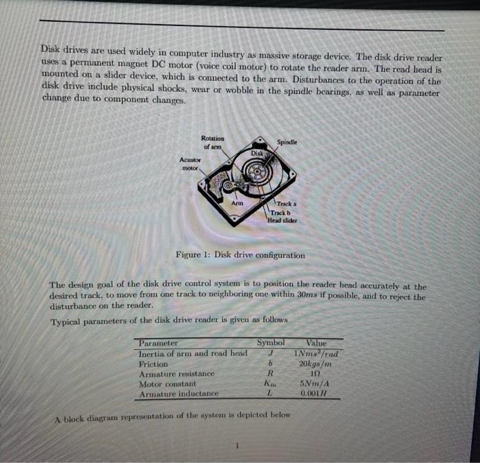
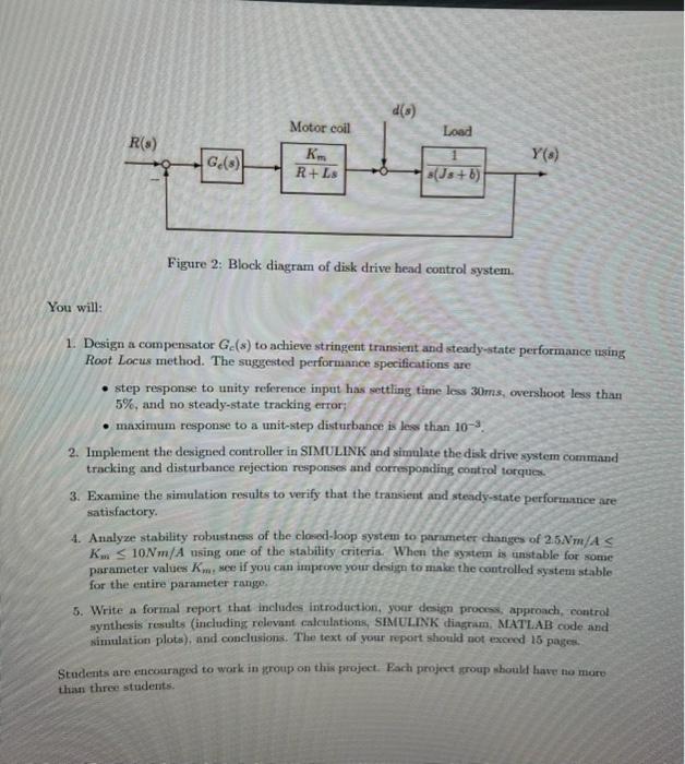
Disk drives are used widely in computer industry as massive storage device. The disk drive reader uses a permanent magnet DC motor (voice coil motor) to rotate the reader arm. The read head is mounted on a slider device, which is connected to the arm. Disturbances to the operation of the disk drive include physical shocks, wear or wobble in the spindle bearings, as well as parameter change due to component changes. Rotation of arm Acuator motor Arm Disk Spindle Parameter Inertia of arm and read head Friction Armature resistance Motor constant Armature inductance Track a Track b Head slider Figure 1: Disk drive configuration The design goal of the disk drive control system is to position the reader head accurately at the desired track, to move from one track to neighboring one within 30ms if possible, and to reject the disturbance on the reader. Typical parameters of the disk drive reader is given as follows Symbol b R Km L A block diagram representation of the system is depicted below Value INms /rad 20kgs/m 5Nm/A 0.001/ R(s) Ge(s) Motor coil Km R+Ls d(s) Load 1 s(Js+b) Figure 2: Block diagram of disk drive head control system. Y(s) You will: 1. Design a compensator Ge(s) to achieve stringent transient and steady-state performance using Root Locus method. The suggested performance specifications are step response to unity reference input has settling time less 30ms, overshoot less than 5%, and no steady-state tracking error; maximum response to a unit-step disturbance is less than 10-. 2. Implement the designed controller in SIMULINK and simulate the disk drive system command tracking and disturbance rejection responses and corresponding control torques. 3. Examine the simulation results to verify that the transient and steady-state performance are satisfactory. 4. Analyze stability robustness of the closed-loop system to parameter changes of 2.5Nm/A < K10Nm/A using one of the stability criteria. When the system is unstable for some parameter values Km. see if you can improve your design to make the controlled system stable for the entire parameter range. 5. Write a formal report that includes introduction, your design process, approach, control synthesis results (including relevant calculations, SIMULINK diagram, MATLAB code and simulation plots), and conclusions. The text of your report should not exceed 15 pages. Students are encouraged to work in group on this project. Each project group should have no more than three students.
Step by Step Solution
★★★★★
3.45 Rating (145 Votes )
There are 3 Steps involved in it
Step: 1

Get Instant Access to Expert-Tailored Solutions
See step-by-step solutions with expert insights and AI powered tools for academic success
Step: 2

Step: 3

Ace Your Homework with AI
Get the answers you need in no time with our AI-driven, step-by-step assistance
Get Started


