Answered step by step
Verified Expert Solution
Question
1 Approved Answer
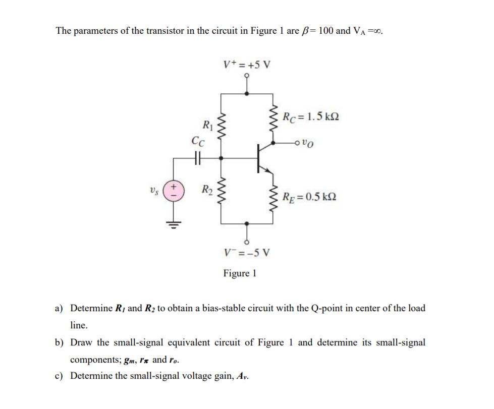
The parameters of the transistor in the circuit in Figure 1 are = 100 and VA =0. Vs R Cc V+ = +5 V

The parameters of the transistor in the circuit in Figure 1 are = 100 and VA =0. Vs R Cc V+ = +5 V www V=-5 V Figure 1 Rc = 1.5 k -000 RE=0.5 k2 a) Determine R, and R to obtain a bias-stable circuit with the Q-point in center of the load line. b) Draw the small-signal equivalent circuit of Figure 1 and determine its small-signal components; gm, rx and ro. c) Determine the small-signal voltage gain, Av.
Step by Step Solution
★★★★★
3.38 Rating (157 Votes )
There are 3 Steps involved in it
Step: 1
Question Given B 100 V 80 A R R V5V v 5V q 5V R 15KR R Q5k2 V25V ITER ...
Get Instant Access to Expert-Tailored Solutions
See step-by-step solutions with expert insights and AI powered tools for academic success
Step: 2

Step: 3

Ace Your Homework with AI
Get the answers you need in no time with our AI-driven, step-by-step assistance
Get Started


