DO ONLY QUESTION 2 Circuit! Thank you
You are not allowed to use the built-in mux or decoder of Logisim
Using the tunneling feature of Logisim is not allowed
 DO ONLY QUESTION 2 You are not allowed to use the built-in mux or decoder of Logisim
DO ONLY QUESTION 2 Circuit!
DO ONLY QUESTION 2 Circuit! 
DO ONLY QUESTION 2 Circuit!
You are not allowed to use the built-in mux or decoder of Logisim
You are not allowed to use the built-in mux or decoder of Logisim
DO ONLY QUESTION 2 Circuit! 
DO ONLY QUESTION 2 Circuit!  You are not allowed to use the built-in mux or decoder of Logisim
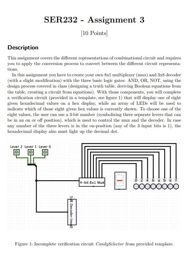
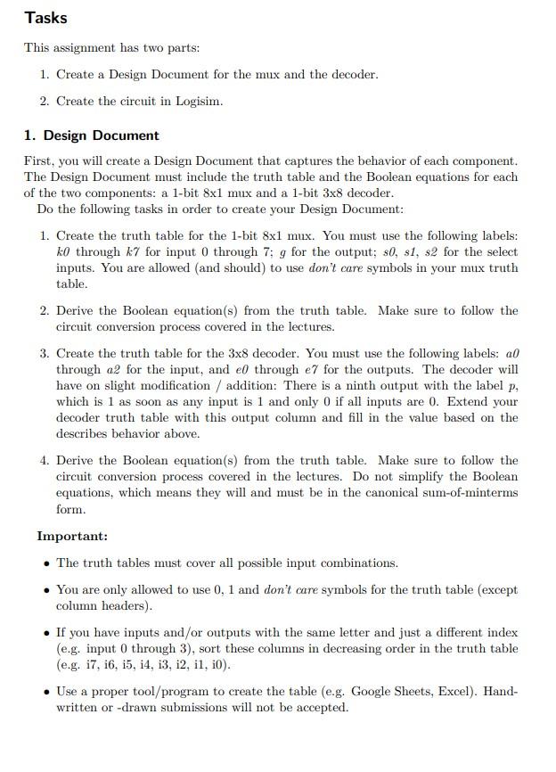
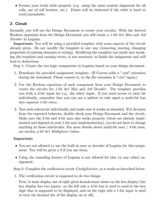
Description This assignment covers the different representations of combinational circuit and requires you to apply the conversion process to convert between the different circuit representations. In this assignment you have to create your own 81 multiplexer (mux) and 38 decoder (with a slight modification) with the three basic logic gates: AND, OR, NOT, using the design process covered in class (designing a truth table, deriving Boolean equations from the table, creating a circuit from equations). With those components, you will complete a verification circuit (provided in a template, see figure 1) that will display one of eight given hexadecimal values on a hex display, while an array of LEDs will be used to indicate which of those eight given hex values is currently shown. To choose one of the eight values, the user can use a 3-bit number (symbolizing three separate levers that can be in an on or off position), which is used to control the mux and the decoder. In case any number of the three levers is in the on-position (any of the 3 input bits is 1), the hexadecimal display also must light up the decimal dot. Figure 1: Incomplete verification circuit CandySelector from provided template. Tasks This assignment has two parts: 1. Create a Design Document for the mux and the decoder. 2. Create the circuit in Logisim. 1. Design Document First, you will create a Design Document that captures the behavior of each component. The Design Document must include the truth table and the Boolean equations for each of the two components: a 1-bit 81 mux and a 1-bit 38 decoder. Do the following tasks in order to create your Design Document: 1. Create the truth table for the 1-bit 81 mux. You must use the following labels: k0 through k7 for input 0 through 7;g for the output; s0,s1,s2 for the select inputs. You are allowed (and should) to use don't care symbols in your mux truth table. 2. Derive the Boolean equation(s) from the truth table. Make sure to follow the circuit conversion process covered in the lectures. 3. Create the truth table for the 38 decoder. You must use the following labels: a0 through a2 for the input, and e0 through e7 for the outputs. The decoder will have on slight modification / addition: There is a ninth output with the label p, which is 1 as soon as any input is 1 and only 0 if all inputs are 0 . Extend your decoder truth table with this output column and fill in the value based on the describes behavior above. 4. Derive the Boolean equation(s) from the truth table. Make sure to follow the circuit conversion process covered in the lectures. Do not simplify the Boolean equations, which means they will and must be in the canonical sum-of-minterms form. Important: - The truth tables must cover all possible input combinations. - You are only allowed to use 0, 1 and don't care symbols for the truth table (except column headers). - If you have inputs and/or outputs with the same letter and just a different index (e.g. input 0 through 3 ), sort these columns in decreasing order in the truth table (e.g. i7, i6, i5, i4, i3, i2, i1, i0). - Use a proper tool/program to create the table (e.g. Google Sheets, Excel). Handwritten or -drawn submissions will not be accepted. - Format your truth table properly (e.g. using the same content alignment for all cells, use of cell borders, etc.). Points will be deducted if the table is hard to read/unreadable. 2. Circuit Secondly, you will use the Design Document to create your circuits. With the derived Boolean equations from the Design Document you will create a 1-bit 8x1 Mux and 3x8 Decoder in Logisim. Important: You will be using a provided template with some aspects of the circuit already given. Do not modify the template in any way (removing, moving, changing properties of existing elements or wiring). Modifying the template can result into breaking the template and causing errors, is not necessary to finish the assignment and will lead to deductions. Step 1: Create the two logic components in Logisim based on your design document. 1. Download the provided assignment template. (If Canvas adds a ".xml" extension during the download: Please remove it, so the file extension is ".circ" again.) 2. Use the Boolean equations of each component from your Design Document to create the circuits for 1 -bit 8x1Mux and 3x8 Decoder. The template provides you with a 3-bit input for e.g., the select input. If you need access to each bit individually, remember that you can use a splitter to take apart a multi-bit bus into separate 1-bit wires. 3. Test each subcircuit individually and make sure it works as intended. If it deviates from the expected behavior, double check your Design Document and the circuit. Make sure the 2-bit and 4-bit mux also works properly (those are already implemented and depend on your 1-bit mux implementation), you do not have to change anything in those subcircuits. For more details about multi-bit mux / 4-bit mux, see section 4-bit 8x1 Multiplexer below. Important: - You are not allowed to use the built-in mux or decoder of Logisim for this assignment. You will be given a 0 if you use them. - Using the tunneling feature of Logisim is not allowed for this (or any other) assignment. Step 2: Complete the verification circuit CandySelector, so it works as described below. 1. The verification circuit is supposed to do two things: First, it must display one of eight given hexadecimal values on the hex display (the hex display has two inputs: on the left side a 4-bit bus is used to send in the hex digit that is supposed to be displayed, and on the right side a 1-bit input is used to turn the decimal dot of the display on or off). Second, an array of LEDs must indicate which of those eight given hex values is currently shown. An LED will turn on/red if it receives a 1 indicating that the value above the LED is being used and should be visible on the hex display. It will turn off if it receives a 0 indicating that the value above it is not being used. Examples: In figure 2 only lever 1 is on (=1) and the others are off (=0). The selected value is this case is 4, which is indicated by the lit red LED below the value. The hex display shows value 4 and the decimal dot is on. Figure 2: Expected output if only lever 1 is on. In figure 3 all levers are off (=0). The selected value in this case is 0, which is indicated by the lit red LED below the value. The hex display shows value 0 and the decimal dot is off (since all three levers are off). Figure 3: Expected output if all levers are off. 2. Think about which of the two logic components can be used to implement each of these two aspects and connect the logic components appropriately with the hex display and the 8 LEDs. The two logic components are already placed in the CandySelector circuit and you only have to add wires to connect everything properly. No other components are required/allowed. 3. To choose one of the eight values, the user can use a 3-bit number (symbolizing three separate levers that can be in an on or off position), which is used to control the mux and the decoder. These are the inputs lever 0,1 and 2 already in the template. If all levers are off (all bits are 0 ), the hex display must show the value 0. 4. Only in case all three levers are in the off-position (all 3 bits are 0), the decimal dot of the hex display should be off (use the right input of the hex display to control the decimal dot), for all other cases the decimal dot must be on. 5. Once you have connected everything, use the Lever inputs to test if your CandySelector circuit and check works properly as described above. 4-bit 81 Multiplexer A 4-bit mux works the same as a 1-bit mux, the only difference is that the inputs and the outputs have 4-bit widths instead of a 1-bit width. Besides this difference the function and behavior is identical. This 4-bit width is necessary for circuits that must select one of multiple 4-bit signals (like in this assignment), which are necessary to represent a hex digit. Deliverables The following deliverables must be submitted on Canvas before the due date as a single submission: 1. Submit your Design Document as .pdf, named: lastname_a3design.pdf 2. Submit your Logisim assignment file, name: lastname_a3.circ Make sure to submit both files in one submission. Only the files of the last submission will be graded. If one is missing, you will receive 0 points for the missing part
 DO ONLY QUESTION 2 You are not allowed to use the built-in mux or decoder of Logisim


 You are not allowed to use the built-in mux or decoder of Logisim


