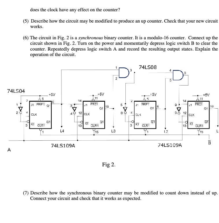
does the clock have any effect on the counter? (5} Describe how the circuit may be modified to produce an up counter. Check that your
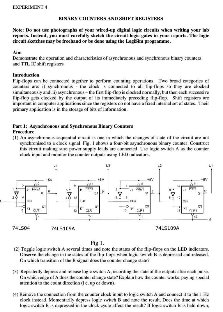
does the clock have any effect on the counter? (5} Describe how the circuit may be modified to produce an up counter. Check that your new circuit works. ({3} The circuit in Fig. 2 is a synchronous binary counter. It is a modulo-lo counter. Connect up the circuit shown in Fig. 2. Turn on the power and momentarily depress logic switch E to clear the counter. Repeatedly depress logic switch A and record the resulting output states. Explain the operation of the circuit. 1 3 F4LSDB Izl D [ ?4LSD4 was-31119.5. F4LSlU9A B Fig 2. (7} Describe how the synchronous hinary counter may be modied to count down instead of up. Connect your circuit and check that it works as expected. EXPERIMENT 4 BINARY CDUNTERS AND SHIFT REGISTERS Note: Do not use photographs of your 1wired-up digital logic circuits when writing your lab reports. Instead, you must carefully sketch the circuit-logic gates in your reports. The logic circuit sketches may he freehand or be done using the LogiSiIn programme. Aim Demonstrate the operation and characteristics of asynchronous and synchronous binary counters and TTL 1C shift registers Introduction Flip-ops can be connected together to perform counting operations. Two broad categories of counters are: i) synchronous the clock is connected to all flipflops so they are clocked simultaneously and. ii) asynchronous the first ip-flop is clocked normally, but then each successive ipop gets clocked by the output of its immediately preceding ipop. Shift registers are important in computer applications since the registers do not have a tted intemai set of states. Their primary application is in the storage of bits of information. Part 1: Asynchronous and Synchronous Binary Counters Procedure {I} An asynchronous sequential circuit is one in which the changes of state of the circuit are not synchronised to a clock signal. Fig. 1 shows a fourhit asynchronous binary counter. Construct this circuit making sure power supply leads are connected. Use logic switch A. as the counter clock. input and monitor the counter outputs Using LED indicators. L4 L3 L2 LI u' _ _ '|11 1d 3 .._.. g o 4% 1 it? 12 IE IE 74LS1U9A T4L5 109A Fig l. (2} Toggle logic switch A several times and note the states of the ip-ops on the LED indicators. Observe the change in the states of the flip-ops when logic switch B is depressed and released. On which transition of the B signal does the counter change state? (3} Repeatedly depress and release logic switch A. recording the state of the outputs after each pulse. [in which edge of A does the counter change state? Explain how the counter works, paying special attention to the count direction {i.e. up or down}. (4} Remove the connection from the counter clock input to logic switch A and connect it to the 1 Hz clock instead. Momentarily depress logic switch B and note the result. Does the time at which logic switch B is depressed in the clock cycle affect the result'.' if logic switch B is held down
Step by Step Solution
There are 3 Steps involved in it
Step: 1
Get Instant Access to Expert-Tailored Solutions
See step-by-step solutions with expert insights and AI powered tools for academic success
Step: 2
Step: 3
Ace Your Homework with AI
Get the answers you need in no time with our AI-driven, step-by-step assistance