

Question
Draw the diagram for circuit which realizes the register transfers below. You are not allowed to use MUX. You can use tri-state buffers. Use registers
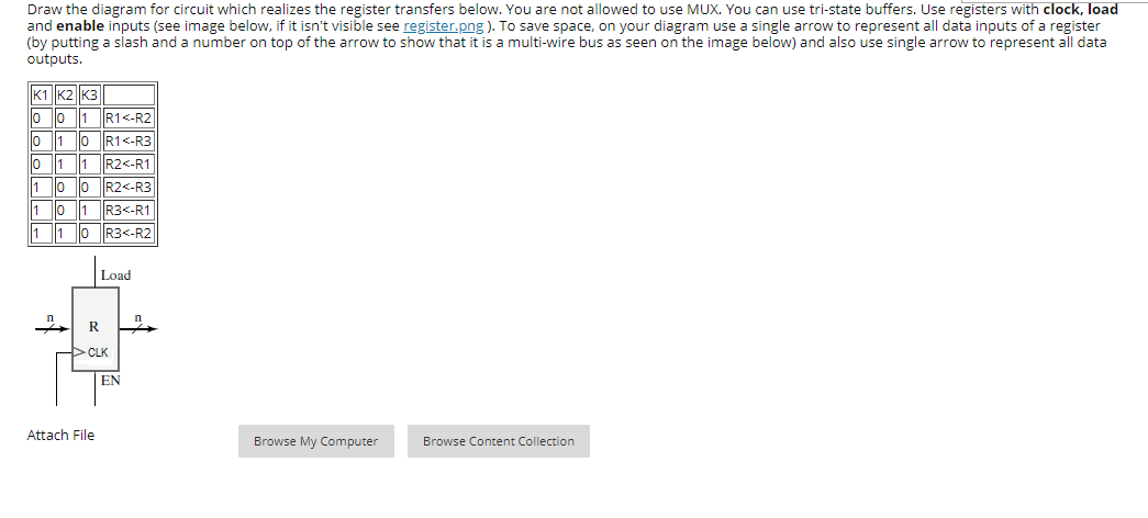
Draw the diagram for circuit which realizes the register transfers below. You are not allowed to use MUX. You can use tri-state buffers. Use registers with clock, load and enable inputs (see image below, if it isn't visible see register.png ). To save space, on your diagram use a single arrow to represent all data inputs of a register (by putting a slash and a number on top of the arrow to show that it is a multi-wire bus as seen on the image below) and also use single arrow to represent all data outputs.
Draw the diagram for circuit which realizes the register transfers below. You are not allowed to use MUX. You can use tri-state buffers. Use registers with clock, load and enable inputs (see image below, if it isn't visible see register.png). To save space, on your diagram use a single arrow to represent all data inputs of a register (by putting a slash and a number on top of the arrow to show that it is a multi-wire bus as seen on the image below) and also use single arrow to represent all data outputs. |K1 K2 K3 o lo 1 R1Step by Step Solution
There are 3 Steps involved in it
Step: 1

Get Instant Access to Expert-Tailored Solutions
See step-by-step solutions with expert insights and AI powered tools for academic success
Step: 2

Step: 3
Ace Your Homework with AI
Get the answers you need in no time with our AI-driven, step-by-step assistance
Get Started
Database Design Application Development And Administration
Authors: Michael V. Mannino
4th Edition
0615231047, 978-0615231044