

Question
Draw the shear force and bending moment diagram for the beam with the loading condition as shown in the figure. Also, determine: (a) o-distribution
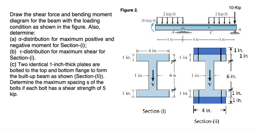
Draw the shear force and bending moment diagram for the beam with the loading condition as shown in the figure. Also, determine: (a) o-distribution for maximum positive and negative moment for Section-(i); (b) T-distribution for maximum shear for Section-(i). (c) Two identical 1-inch-thick plates are bolted to the top and bottom flange to form the built-up beam as shown (Section-(II)). Determine the maximum spacing s of the bolts if each bolt has a shear strength of 5 kip. Figure 2. 1 in. 1 in. 20 kip-ft 1 in.- -4 in. 2 kip/ft Section-(i) -5 ft- 6 it in. 1 in. -5 ft- 1 in- 2 kip/fl -5 ft 4 in. Section-(ii) 10-Kip B3 1 in. 1 in 6 in. 1 in. 1 in.
Step by Step Solution
There are 3 Steps involved in it
Step: 1

Get Instant Access to Expert-Tailored Solutions
See step-by-step solutions with expert insights and AI powered tools for academic success
Step: 2

Step: 3
Ace Your Homework with AI
Get the answers you need in no time with our AI-driven, step-by-step assistance
Get Started
A First Course in the Finite Element Method
Authors: Daryl L. Logan
6th edition
1305635116, 978-1305887176, 1305887174, 978-1305635111