(Due by 02/02/20 midnight) The P-machine: In this assignment, you will implement a virtual machine (VM) known as the P-machine (PM/0). The P-machine is a stack machine with two memory stores: the stack, which is organized as a stack and contains the data to be used by the PM/0 CPU, and the text, which contains the instructions for the VM. The PM/0 CPU has four registers to handle the stack and text segments: The registers are named base pointer (BP), stack pointer (SP), program counter (PC) and instruction register (IR). They will be explained in detail later on in this document. The machine also has a register file (RF) with eight (8) registers (0-7). The Instruction Set Architecture (ISA) of the PM/0 has 24 instructions and the instruction format is as follows: OP R L M
Each instruction contains four components (OP R L M) that are separated by one space.
OP is the operation code. R refers to a register L indicates the lexicographical level or a register in arithmetic and relational instructions. M depending of the operators it indicates: - A number (instructions: LIT, INC). - A program address (instructions: JMP, JPC, CAL). - A data address (instructions: LOD, STO) - A register in arithmetic and logic instructions. (e.g. ADD R[1], R[2], R[3] )
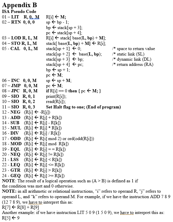
The list of instructions for the ISA can be found in Appendix A and B.
P-Machine Cycles
The PM/0 instruction cycle is carried out in two steps. This means that it executes two steps for each instruction. The first step is the Fetch Cycle, where the actual instruction is fetched from the text memory store and place in the instruction register. The second step is the Execute Cycle, where the instruction that was fetched is executed using the stack memory store and the register file (RF). This does not mean the instruction is stored in the stack.
Fetch Cycle: In the Fetch Cycle, an instruction is fetched from the text store and placed in the IR register (IR
Execute Cycle: In the Execute Cycle, the instruction that was fetched is executed by the VM. The OP component that is stored in the IR register (IR.OP) indicates the operation to be executed. For example, if IR.OP is the instruction ADD (IR.OP = 12), then R, L, M components of the instruction in IR (IR.R, IR.L, IR.M) are used as registers numbers to execute the instruction ADD (IR.R
PM/0 Initial/Default Values:
Initial values for PM/0 CPU registers: SP = 0; BP = 1; PC = 0; IR = 0;
Initial stack store values are all zero: stack[1] =0, stack[2] =0, stack[3] =0..stack[39] = 0.
All registers in the register file have initial value zero (R0 = 0, R1= 0, R3 = 0.R7 = 0.
Constant Values: MAX_STACK_HEIGHT is 40 MAX_CODE_LENGTH is 200 MAX_LEXI_LEVELS is 3
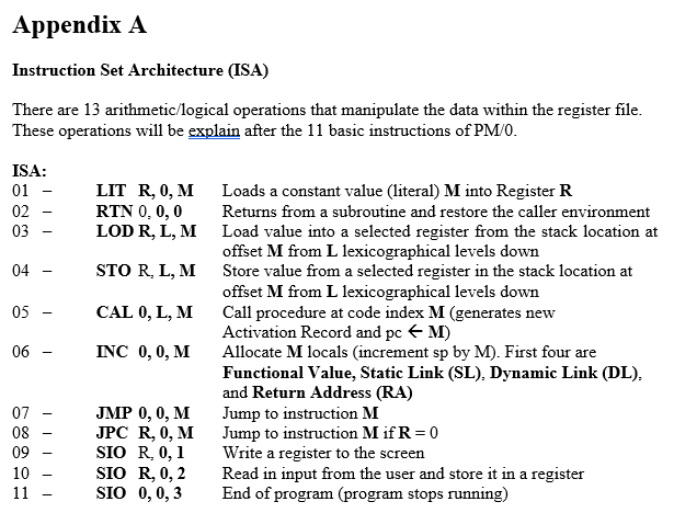
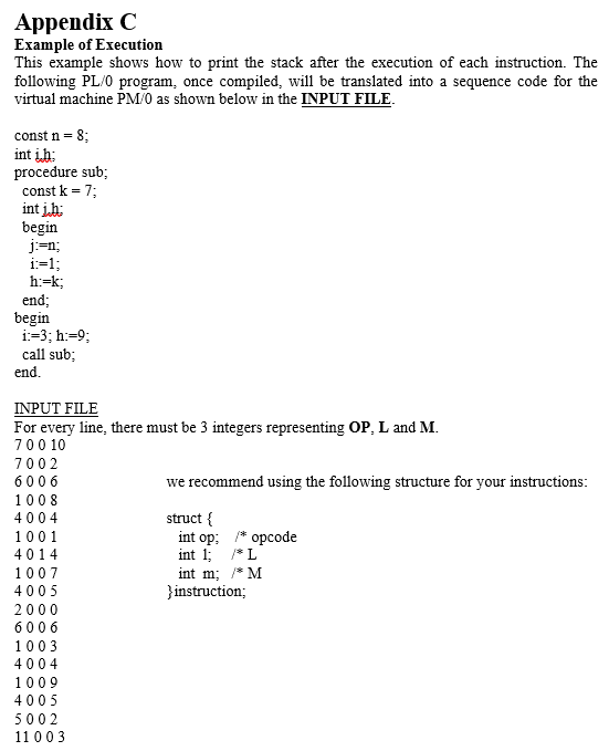
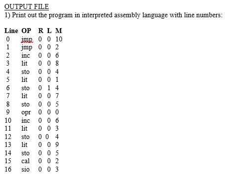
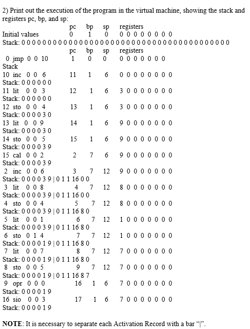
Appendix A Instruction Set Architecture (ISA) There are 13 arithmetic/logical operations that manipulate the data within the register file. These operations will be explain after the 11 basic instructions of PM/O. ISA: LIT R, 0, M RTN 0, 0,0 LOD R, L,M STO R,L,M CAL 0, L, M - INC 0,0,M Loads a constant value (literal) M into Register R Returns from a subroutine and restore the caller environment Load value into a selected register from the stack location at offset M from L lexicographical levels down Store value from a selected register in the stack location at offset M from L lexicographical levels down Call procedure at code index M (generates new Activation Record and pc M) Allocate M locals (increment sp by M). First four are Functional Value, Static Link (SL), Dynamic Link (DL), and Return Address (RA) Jump to instruction M Jump to instruction M if R=0 Write a register to the screen Read in input from the user and store it in a register End of program (program stops running) T 08 - 09 - 10 - 11 - JMP 0, 0, M JPC R, 0, M SIO R. 0,1 SIO R, 0,2 SIO 0,0,3 Appendix B ISA Pseudo Code 01 - LIT R, 0, M R[i] M; 02 - RTN 0,0,0 sp bp - 1; bp stack[sp + 3); pc stack[sp + 4); 03- LOD R, L,M R[i] stack[ base(L, bp) + M); 04 - STOR, L, M stack base(L, bp) + M] R[i]; 05 - CAL 0,L,M stack[sp + 1] 0: /* space to return value stack[sp + 2] + base(L, bp); /* static link (SL) stack[sp +3]
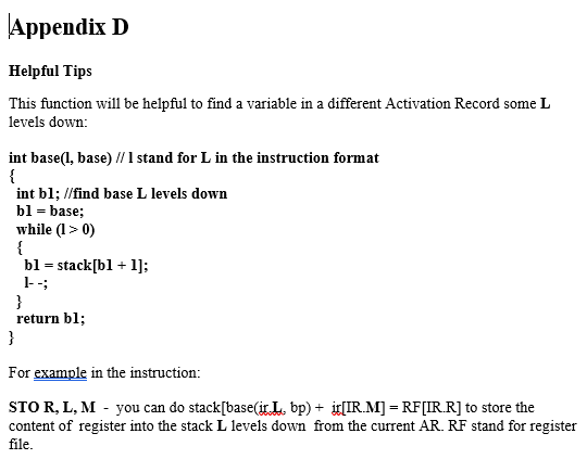
R[k]) 24 - GEQ (R[i] R[] >=R[k]) NOTE: The result of a logical operation such as (A >B) is defined as 1 if the condition was met and 0 otherwise. NOTE: in all arithmetic or relational instructions, "1" refers to operand R, j' refers to operand L, and k refers to operand M. For example, if we have the instruction ADD 7 8 9 (12 7 8 9), we have to interpret this as: R[7] R[8] +R[9] Another example: if we have instruction LIT 5 0 9 (1 509), we have to interpret this as: R[5] 9 Appendix C Example of Execution This example shows how to print the stack after the execution of each instruction. The following PL/O program, once compiled, will be translated into a sequence code for the virtual machine PM/0 as shown below in the INPUT FILE. const n = 8; intih: procedure sub; const k = 7; intih: begin j:=n; i=1; h:=k; end; begin i:=3;h:=9; call sub; end. INPUT FILE For every line, there must be 3 integers representing OP, L and M. 70 0 10 7002 6006 we recommend using the following structure for your instructions: 1008 4004 struct { 1001 int op: /* opcode 4014 int 1; /*L 1007 int m; /*M 4005 }instruction; 2000 6 006 1003 4004 1009 4005 5002 11 003 OUTPUT FILE 1) Print out the program in interpreted assembly language with line numbers: Line OP RLM O jmp 0 0 10 1 jmp 0 0 2 2 inc006 3 lit 008 4 sto 004 5 lit001 sto 0 14 lit 0 0 7 sto 0 0 5 opr000 inc006 11 lit 0 0 3 12 sto 004 13 lit009 14 sto 0 0 5 15 cal 0 0 2 16 sio 0 0 3 2) Print out the execution of the program in the virtual machine, showing the stack and registers pc, bp, and sp: pcbpsp registers Initial values 0 1 0 00000000 Stack: 0000000000000000000000000000000000000000 pcbpsp registers O jmp 0 0 10 1 0 0 0000000 Stack 10 inc006 11 1 6 0000 0 0 0 0 Stack: 0 0 0 0 0 0 11 lit 003 12 1 6 3000 0 0 0 0 Stack: 0 0 0 0 0 0 12 sto 0 0 4 13 1 6 3000 0 0 0 0 Stack: 0 0 0 0 3 0 13 lit 0 0 9 14 1 6 9000 0 0 0 0 Stack: 000030 14 sto 0 0 5 15 16 00000000 Stack: 0 0 0 0 39 15 cal 0 0 2 2 7 6 90000000 Stack: 0 0 0 0 39 2 inc 0 0 6 3 7 12 900 0 0 0 0 0 Stack: 0 0 0 0 3 9 10 11 16 0 0 3 lit 008 4 7 12 8 0 0 0 0 0 0 0 Stack: 0 0 0 0 3 9 10 11 16 0 0 4 sto 0 0 4 5 7 12 8 0 0 0 0 0 0 0 Stack: 0 0 0 0 3 9011 16 8 0 5 lit 001 6 7 12 1000 0 0 0 0 Stack: 0 0 0 0 3 9011 16 8 0 6 sto 0 1 4 7 7 12 1000 0 0 0 0 Stack: 000019011 16 8 0 7 lit 007 8 7 12 700 0 0 0 0 0 Stack: 0 0 0 019 011 16 80 8 sto 0 0 5 9 7 12 70000000 Stack: 000019011 1687 9 opr 000 16 16 700 0 0 0 0 0 Stack: 000019 16 sio 003 17 16 700 0 0 0 0 0 Stack: 000019 NOTE: It is necessary to separate each Activation Record with a bar "". Appendix D Helpful Tips This function will be helpful to find a variable in a different Activation Record some L levels down: int base(1, base) // I stand for L in the instruction format int bl; //find base L levels down bl = base; while ( 10) bl = stack[bl + 1]; 1- return bl; For example in the instruction: STOR, L, M - you can do stack[base(ir L bp) + ir[IR.M] = RF[IR.R] to store the content of register into the stack L levels down from the current AR. RF stand for register file. Appendix A Instruction Set Architecture (ISA) There are 13 arithmetic/logical operations that manipulate the data within the register file. These operations will be explain after the 11 basic instructions of PM/O. ISA: LIT R, 0, M RTN 0, 0,0 LOD R, L,M STO R,L,M CAL 0, L, M - INC 0,0,M Loads a constant value (literal) M into Register R Returns from a subroutine and restore the caller environment Load value into a selected register from the stack location at offset M from L lexicographical levels down Store value from a selected register in the stack location at offset M from L lexicographical levels down Call procedure at code index M (generates new Activation Record and pc M) Allocate M locals (increment sp by M). First four are Functional Value, Static Link (SL), Dynamic Link (DL), and Return Address (RA) Jump to instruction M Jump to instruction M if R=0 Write a register to the screen Read in input from the user and store it in a register End of program (program stops running) T 08 - 09 - 10 - 11 - JMP 0, 0, M JPC R, 0, M SIO R. 0,1 SIO R, 0,2 SIO 0,0,3 Appendix B ISA Pseudo Code 01 - LIT R, 0, M R[i] M; 02 - RTN 0,0,0 sp bp - 1; bp stack[sp + 3); pc stack[sp + 4); 03- LOD R, L,M R[i] stack[ base(L, bp) + M); 04 - STOR, L, M stack base(L, bp) + M] R[i]; 05 - CAL 0,L,M stack[sp + 1] 0: /* space to return value stack[sp + 2] + base(L, bp); /* static link (SL) stack[sp +3] R[k]) 24 - GEQ (R[i] R[] >=R[k]) NOTE: The result of a logical operation such as (A >B) is defined as 1 if the condition was met and 0 otherwise. NOTE: in all arithmetic or relational instructions, "1" refers to operand R, j' refers to operand L, and k refers to operand M. For example, if we have the instruction ADD 7 8 9 (12 7 8 9), we have to interpret this as: R[7] R[8] +R[9] Another example: if we have instruction LIT 5 0 9 (1 509), we have to interpret this as: R[5] 9 Appendix C Example of Execution This example shows how to print the stack after the execution of each instruction. The following PL/O program, once compiled, will be translated into a sequence code for the virtual machine PM/0 as shown below in the INPUT FILE. const n = 8; intih: procedure sub; const k = 7; intih: begin j:=n; i=1; h:=k; end; begin i:=3;h:=9; call sub; end. INPUT FILE For every line, there must be 3 integers representing OP, L and M. 70 0 10 7002 6006 we recommend using the following structure for your instructions: 1008 4004 struct { 1001 int op: /* opcode 4014 int 1; /*L 1007 int m; /*M 4005 }instruction; 2000 6 006 1003 4004 1009 4005 5002 11 003 OUTPUT FILE 1) Print out the program in interpreted assembly language with line numbers: Line OP RLM O jmp 0 0 10 1 jmp 0 0 2 2 inc006 3 lit 008 4 sto 004 5 lit001 sto 0 14 lit 0 0 7 sto 0 0 5 opr000 inc006 11 lit 0 0 3 12 sto 004 13 lit009 14 sto 0 0 5 15 cal 0 0 2 16 sio 0 0 3 2) Print out the execution of the program in the virtual machine, showing the stack and registers pc, bp, and sp: pcbpsp registers Initial values 0 1 0 00000000 Stack: 0000000000000000000000000000000000000000 pcbpsp registers O jmp 0 0 10 1 0 0 0000000 Stack 10 inc006 11 1 6 0000 0 0 0 0 Stack: 0 0 0 0 0 0 11 lit 003 12 1 6 3000 0 0 0 0 Stack: 0 0 0 0 0 0 12 sto 0 0 4 13 1 6 3000 0 0 0 0 Stack: 0 0 0 0 3 0 13 lit 0 0 9 14 1 6 9000 0 0 0 0 Stack: 000030 14 sto 0 0 5 15 16 00000000 Stack: 0 0 0 0 39 15 cal 0 0 2 2 7 6 90000000 Stack: 0 0 0 0 39 2 inc 0 0 6 3 7 12 900 0 0 0 0 0 Stack: 0 0 0 0 3 9 10 11 16 0 0 3 lit 008 4 7 12 8 0 0 0 0 0 0 0 Stack: 0 0 0 0 3 9 10 11 16 0 0 4 sto 0 0 4 5 7 12 8 0 0 0 0 0 0 0 Stack: 0 0 0 0 3 9011 16 8 0 5 lit 001 6 7 12 1000 0 0 0 0 Stack: 0 0 0 0 3 9011 16 8 0 6 sto 0 1 4 7 7 12 1000 0 0 0 0 Stack: 000019011 16 8 0 7 lit 007 8 7 12 700 0 0 0 0 0 Stack: 0 0 0 019 011 16 80 8 sto 0 0 5 9 7 12 70000000 Stack: 000019011 1687 9 opr 000 16 16 700 0 0 0 0 0 Stack: 000019 16 sio 003 17 16 700 0 0 0 0 0 Stack: 000019 NOTE: It is necessary to separate each Activation Record with a bar "". Appendix D Helpful Tips This function will be helpful to find a variable in a different Activation Record some L levels down: int base(1, base) // I stand for L in the instruction format int bl; //find base L levels down bl = base; while ( 10) bl = stack[bl + 1]; 1- return bl; For example in the instruction: STOR, L, M - you can do stack[base(ir L bp) + ir[IR.M] = RF[IR.R] to store the content of register into the stack L levels down from the current AR. RF stand for register file


