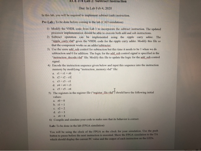
ECE 374 Lab 2: Subtract Instruction Due: In Lab Feb 4, 2020 In this lab, you will be required to implement subtract (sub) instruction. Pre-Lab: To be done before coming to the lab (CAD simulation) 1) Modify the VHDL code from Lab I to incorporate the subtract instruction. The updated processor implementation should be able to execute both add and sub instructions 2) Subtract operation can be implemented using the ripple carry adder. The ripple carry.vhd" gives the VHDL code for the ripple carry adder. Modify this file so that the component works as an adder/subtracter. 3) Use the same add sub control for subtraction but this time it needs to be 1 when we do subtraction and 0 for addition. The logic for the add sub control signal is specified in the "instruction decode.vhd file. Modify this file to update the logic for the add sub control signal. 4) Encode the instruction sequence given below and input this sequence into the instruction memory by modifying "instruction memory.vhd" file: a. rl=rl + 10 b. r2 = r2 - 1 c. 13 =13-11 d. 14-14+r3 e. 15 = 15-14 5) The registers in the register file ("register file.vhd should have the following initial values: a 100 b. r1 - 1 c. 12-2 d. 13-3 e. 44 6) Compile and simulate your code to make sure that its behavior is correct. Lab: To be done in the lab (FPGA simulation) You will be using the clock of the FPGA as the clock for your simulation. Use the push button to pause before the next instruction is executed. Show the FPGA simulation to the TA which should display the current PC value and the output of each instruction on the LEDs ECE 374 Lab 2: Subtract Instruction Due: In Lab Feb 4, 2020 In this lab, you will be required to implement subtract (sub) instruction. Pre-Lab: To be done before coming to the lab (CAD simulation) 1) Modify the VHDL code from Lab I to incorporate the subtract instruction. The updated processor implementation should be able to execute both add and sub instructions 2) Subtract operation can be implemented using the ripple carry adder. The ripple carry.vhd" gives the VHDL code for the ripple carry adder. Modify this file so that the component works as an adder/subtracter. 3) Use the same add sub control for subtraction but this time it needs to be 1 when we do subtraction and 0 for addition. The logic for the add sub control signal is specified in the "instruction decode.vhd file. Modify this file to update the logic for the add sub control signal. 4) Encode the instruction sequence given below and input this sequence into the instruction memory by modifying "instruction memory.vhd" file: a. rl=rl + 10 b. r2 = r2 - 1 c. 13 =13-11 d. 14-14+r3 e. 15 = 15-14 5) The registers in the register file ("register file.vhd should have the following initial values: a 100 b. r1 - 1 c. 12-2 d. 13-3 e. 44 6) Compile and simulate your code to make sure that its behavior is correct. Lab: To be done in the lab (FPGA simulation) You will be using the clock of the FPGA as the clock for your simulation. Use the push button to pause before the next instruction is executed. Show the FPGA simulation to the TA which should display the current PC value and the output of each instruction on the LEDs


