

Question: EEN 2 2 0 - Electric Circuits II: Course Project Description Calculating Power in Balanced & Unbalanced Three Phase Circuits using Matlab / Simulink Project
EEN Electric Circuits II: Course Project Description
Calculating Power in Balanced & Unbalanced Three Phase Circuits using MatlabSimulink
Project Description:
In this project, you'll embark on a comprehensive exploration of threephase power systems using MatlabSimulink Your tasks will encompass four distinct scenarios, where you'll be tasked with determining the complex power real power reactive power of the load, along with assessing the power factor and power losses in the line after incorporating the line impedance Zline Additionally, you'll be required to plot voltage and current values both phase and line quantities of the load in each of the four scenarios. These scenarios will cover both Wye configurations balanced and unbalanced as well as Delta configurations balanced and unbalanced
The project can be broken down into the following steps:
Design and Implement a ThreePhase Power System:
Create threephase power system models in MatlabSimulink for each of the four system configurations specified in the coming section and based on the example shown in Figure
Do the Calculations
Solve the system using circuit analysis to find the required measurements in the system and compare the calculated values with simulated measurements.
System Measurements:
Utilize MatlabSimulinks advanced tools to precisely measure the currents, voltages, complex power S real power P reactive power Q of the load.
Power Factor and Losses Measurements:
Utilize MatlabSimulink to measure the power factor of the load and power losses in the line after adding Zline
Plotting Voltages and Currents
Use MatlabSimulink to plot the currents and voltages phase and line of the load in all the four scenarios.
of
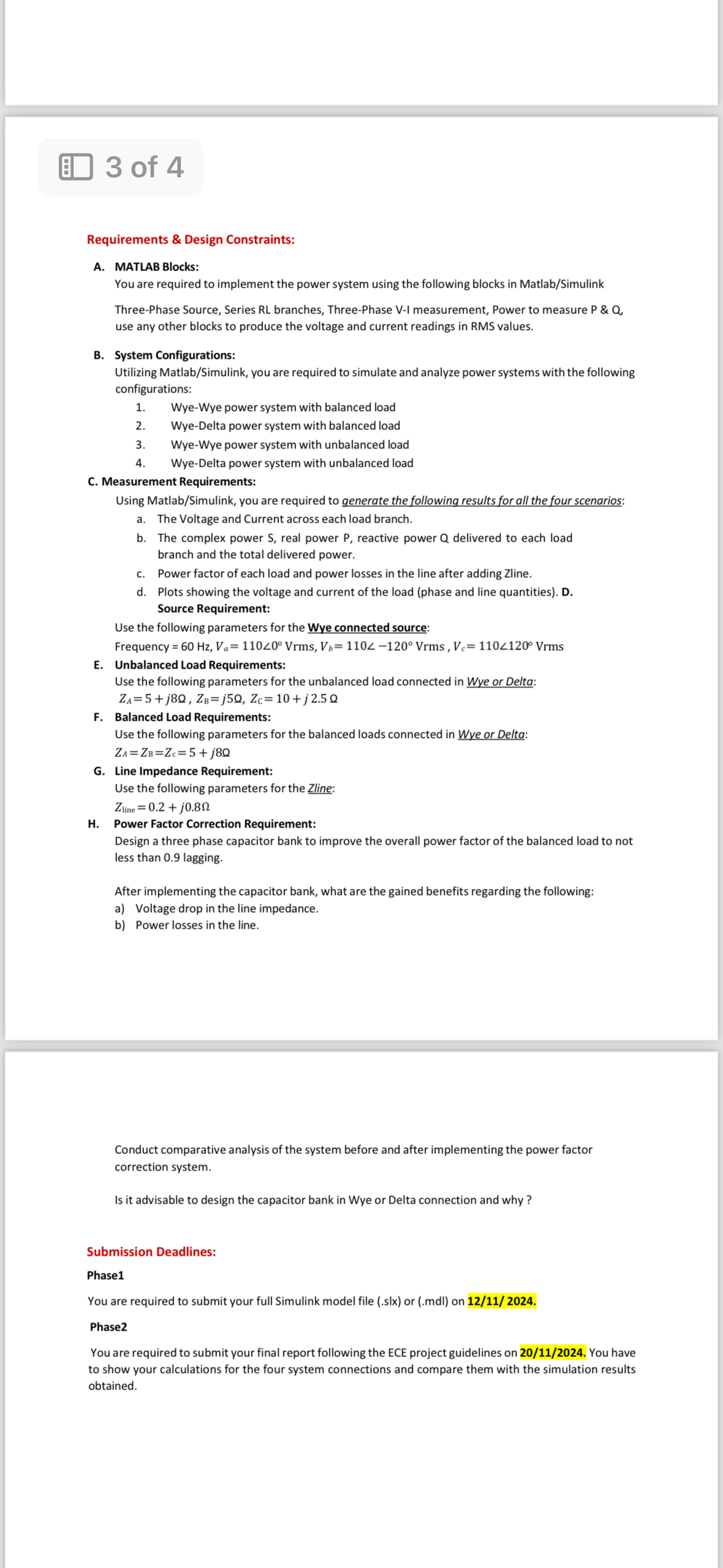
Requirements & Design Constraints:
A MATLAB Blocks:
You are required to implement the power system using the following blocks in MatlabSimulink
ThreePhase Source, Series RL branches, ThreePhase VI measurement, Power to measure P & Q use any other blocks to produce the voltage and current readings in RMS values.
B System Configurations:
Utilizing MatlabSimulink you are required to simulate and analyze power systems with the following configurations:
WyeWye power system with balanced load
WyeDelta power system with balanced load
WyeWye power system with unbalanced load
WyeDelta power system with unbalanced load
C Measurement Requirements:
Using MatlabSimulink you are required to generate the following results for all the four scenarios:
a The Voltage and Current across each load branch.
b The complex power real power reactive power delivered to each load branch and the total delivered power.
c Power factor of each load and power losses in the line after adding Zline.
d Plots showing the voltage and current of the load phase and line quantities D Source Requirement:
Use the following parameters for the Wye connected source:
Frequency
E Unbalanced Load Requirements:
Use the following parameters for the unbalanced load connected in Wye or Delta:
Q
F Balanced Load Requirements:
Use the following parameters for the balanced loads connected in Wye or Delta:
G Line Impedance Requirement:
Use the following parameters for the Zline:
H Power Factor Correction Requirement:
Design a three phase capacitor bank to improve the overall power factor of the balanced load to not less than lagging.
After implementing the capacitor bank, what are the gained benefits regarding the following:
a Voltage drop in the line impedance.
b Power losses in the line.
Conduct comparative analysis of the system before and after implementing the power factor correction system.
Is it advisable to design the capacitor bank in Wye or Delta connection and why
Submission Deadlines:
Phase
You are required to submit your full Simulink model file slx or mdl on
Phase
You are required to submit your final report following the ECE project guidelines on You have to show your calculations for the four system connections and compare them with the simulation results obtained.
Step by Step Solution
There are 3 Steps involved in it
1 Expert Approved Answer
Step: 1 Unlock

Question Has Been Solved by an Expert!
Get step-by-step solutions from verified subject matter experts
Step: 2 Unlock
Step: 3 Unlock