

Answered step by step
Verified Expert Solution
Question
1 Approved Answer
electrode relative to the other. It is recommended to adjust the power supply to supply 6 Volts of potential. A U- shaped probe or wand
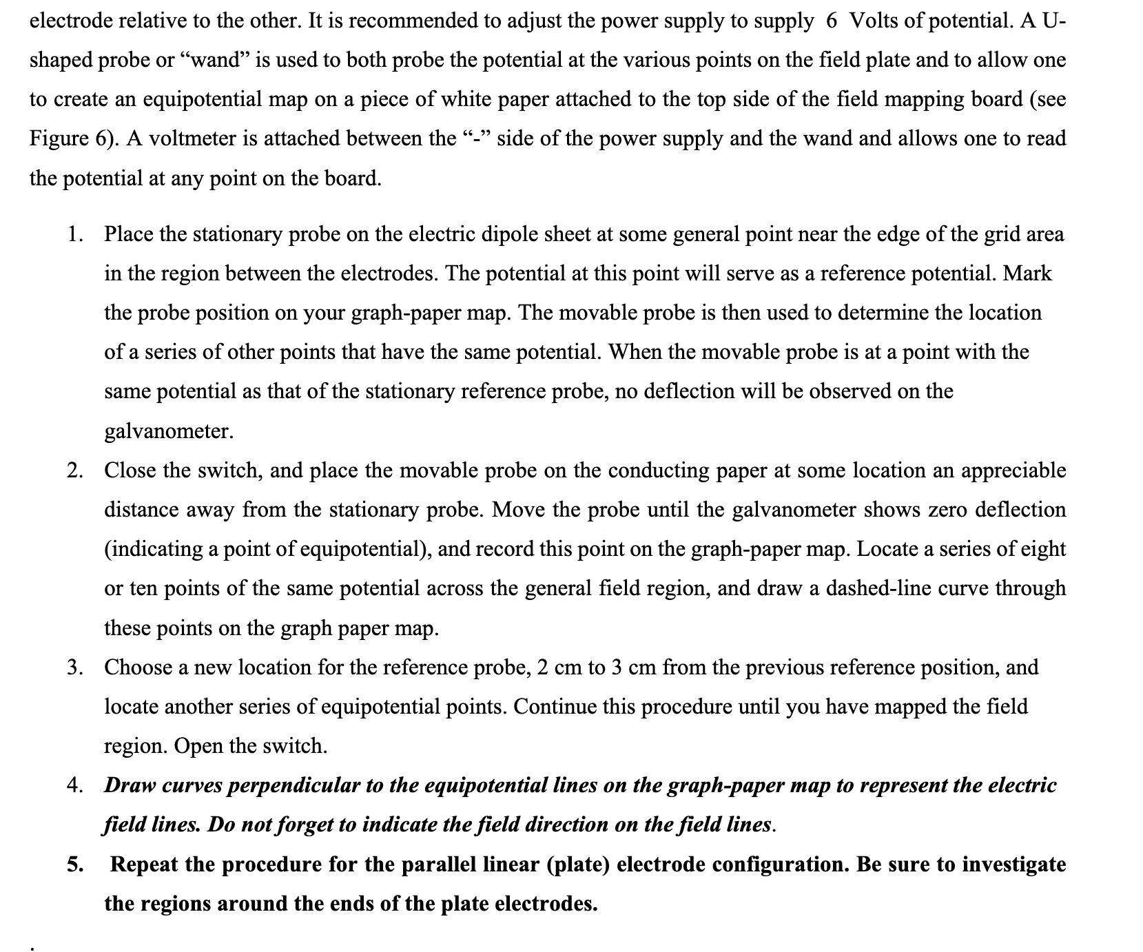 electrode relative to the other. It is recommended to adjust the power supply to supply 6 Volts of potential. A U- shaped probe or "wand" is used to both probe the potential at the various points on the field plate and to allow one to create an equipotential map on a piece of white paper attached to the top side of the field mapping board (see Figure 6). A voltmeter is attached between the "-" side of the power supply and the wand and allows one to read the potential at any point on the board. 1. Place the stationary probe on the electric dipole sheet at some general point near the edge of the grid area in the region between the electrodes. The potential at this point will serve as a reference potential. Mark the probe position on your graph-paper map. The movable probe is then used to determine the location of a series of other points that have the same potential. When the movable probe is at a point with the same potential as that of the stationary reference probe, no deflection will be observed on the galvanometer. 2. Close the switch, and place the movable probe on the conducting paper at some location an appreciable distance away from the stationary probe. Move the probe until the galvanometer shows zero deflection (indicating a point of equipotential), and record this point on the graph-paper map. Locate a series of eight or ten points of the same potential across the general field region, and draw a dashed-line curve through these points on the graph paper map. 3. Choose a new location for the reference probe, 2 cm to 3 cm from the previous reference position, and locate another series of equipotential points. Continue this procedure until you have mapped the field region. Open the switch. 4. Draw curves perpendicular to the equipotential lines on the graph-paper map to represent the electric field lines. Do not forget to indicate the field direction on the field lines. 5. Repeat the procedure for the parallel linear (plate) electrode configuration. Be sure to investigate the regions around the ends of the plate electrodes
Step by Step Solution
There are 3 Steps involved in it
Step: 1

Get Instant Access to Expert-Tailored Solutions
See step-by-step solutions with expert insights and AI powered tools for academic success
Step: 2

Step: 3
Ace Your Homework with AI
Get the answers you need in no time with our AI-driven, step-by-step assistance
Get Started
International Economics Theory and Policy
Authors: Paul R. Krugman, Maurice Obstfeld, Marc J. Melitz
9th Edition
978-0132146654, 0132146657, 9780273754091, 978-0273754206