Answered step by step
Verified Expert Solution
Question
1 Approved Answer
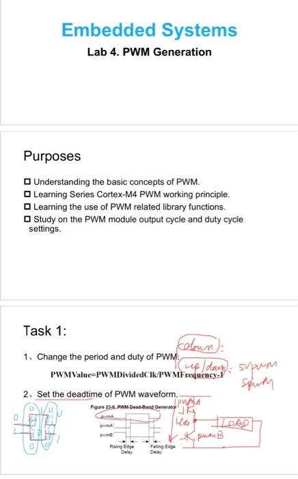
Embedded system lab homework, i will give thumbs up for the answers Embedded Systems Lab 4. PWM Generation Purposes Understanding the basic concepts of PWM.
Embedded system lab homework, i will give thumbs up for the answers 

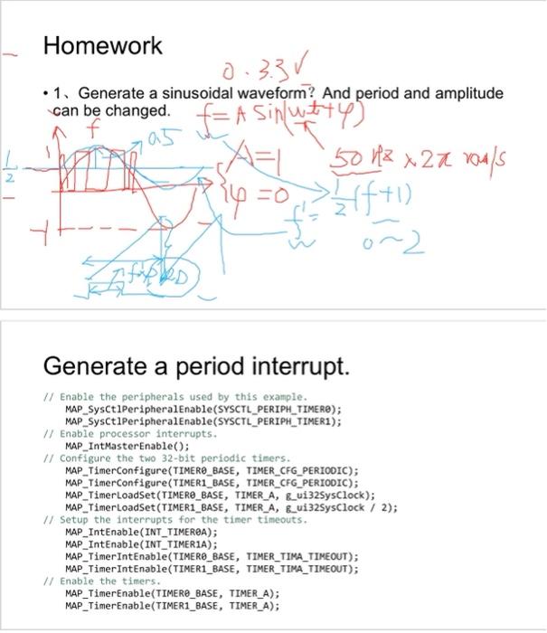
Embedded Systems Lab 4. PWM Generation Purposes Understanding the basic concepts of PWM. Learning Series Cortex-M4 PWM working principle. Learning the use of PWM related library functions. Study on the PWM module output cycle and duty cycle settings. Task 1: 1. Change the period and duty of PWM. PWMValue=PWMDividedClk/PWMFrequency- 1 2 Set the deadtime of PWM waveform. ion1A - 1 Generate a sinusoidal waveform? And period and amplitude can be changed. Generate a period interrupt. II Enable the peripherals used by this example. MAP_SysCt1Periphera1Enable(SYSCTL_PERIPH_TIMER); MAP_SysCt1PeripheralEnable(SYSCTL_PERIPH_TIMER1); // Enable processor interrupts. MAP_IntMasterEnable(); 1/ Configure the two 32-bit periodic timers. MAP_TimerConfigure(TIMERO_BASE, TIMER_CFG_PERIOOIC); MAP_TimerConfigure(TIMER1_BASE, TIMER_CFG_PERIOOIC); MAP_TimerLoadSet(TIMERO_BASE, TIMER_A, G_ui325ysClock); MAP_TimerLoadSet(TIMER1_BASE, TIMER_A, B_ui32SysClock / 2); 1/ Setup the interrupts for the timer timeouts. MAP_IntEnable(INT_TIMEREA); MAP_IntEnable(INT_TIMER1A); MAP_TimerIntEnable(TIMERO_BASE, TIMER_TIMA_TIMEOUT); MAP_TimerIntEnable(TIMER1_BASE, TIMER_TIMA_TIMEOUT); 1/ Enable the timers. MAP_TimerEnable(TIMER_BASE, TIMER_A); MAP_TimerEnable(TIMER1_BASE, TIMER_A) 

Step by Step Solution
There are 3 Steps involved in it
Step: 1

Get Instant Access to Expert-Tailored Solutions
See step-by-step solutions with expert insights and AI powered tools for academic success
Step: 2

Step: 3

Ace Your Homework with AI
Get the answers you need in no time with our AI-driven, step-by-step assistance
Get Started


