Answered step by step
Verified Expert Solution
Question
1 Approved Answer
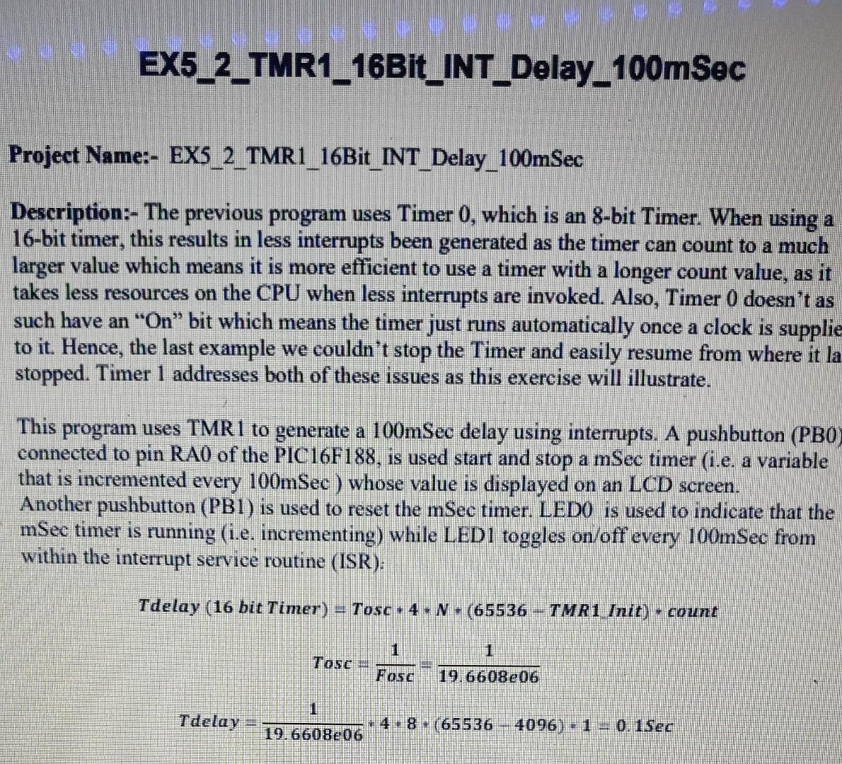
EX5_2_TMR1_16Bit_INT_Delay_100msec Project Name:- EX5_2_TMR1_16Bit_INT_Delay_100mSec Description:- The previous program uses Timer 0 , which is an 8-bit Timer. When using a 16-bit timer, this results in

EX5_2_TMR1_16Bit_INT_Delay_100msec Project Name:- EX5_2_TMR1_16Bit_INT_Delay_100mSec Description:- The previous program uses Timer 0 , which is an 8-bit Timer. When using a 16-bit timer, this results in less interrupts been generated as the timer can count to a much larger value which means it is more efficient to use a timer with a longer count value, as it takes less resources on the CPU when less interrupts are invoked. Also, Timer 0 doesn't as such have an "On" bit which means the timer just runs automatically once a clock is supplie to it. Hence, the last example we couldn't stop the Timer and easily resume from where it la stopped. Timer 1 addresses both of these issues as this exercise will illustrate. This program uses TMR1 to generate a 100mSec delay using interrupts. A pushbutton ( PB0 ) connected to pin RA0 of the PIC16F188, is used start and stop a mSec timer (i.e. a variable that is incremented every 100mSec ) whose value is displayed on an LCD screen. Another pushbutton ( PB1 ) is used to reset the mSec timer. LED0 is used to indicate that the mSec timer is running (i.e. incrementing) while LED1 toggles on/off every 100mSec from within the interrupt service routine (ISR): Tdelay(16bitTimer)=Tosc4N(65536TMR1Init)countTosc=Fosc1=19.6608e061Tdelay=19.6608e06148(655364096)1=0.1Sec
Step by Step Solution
There are 3 Steps involved in it
Step: 1

Get Instant Access to Expert-Tailored Solutions
See step-by-step solutions with expert insights and AI powered tools for academic success
Step: 2

Step: 3

Ace Your Homework with AI
Get the answers you need in no time with our AI-driven, step-by-step assistance
Get Started


